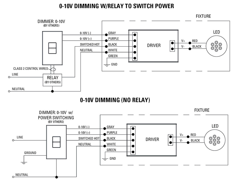
A V dimmer is considered analog dimming, and all USAI V dimming options are considered to be “sink” type dimming. A typical V wiring diagram is. 0–10 V control link controls third party fixtures. • DVSTV- wires as single pole or 3 -way, dimming performance.
. Wiring Diagram Using a Power Pack. 0– For use with fixtures using V dimmable power supply/drivers, Advance Transformer Mark 7®,.
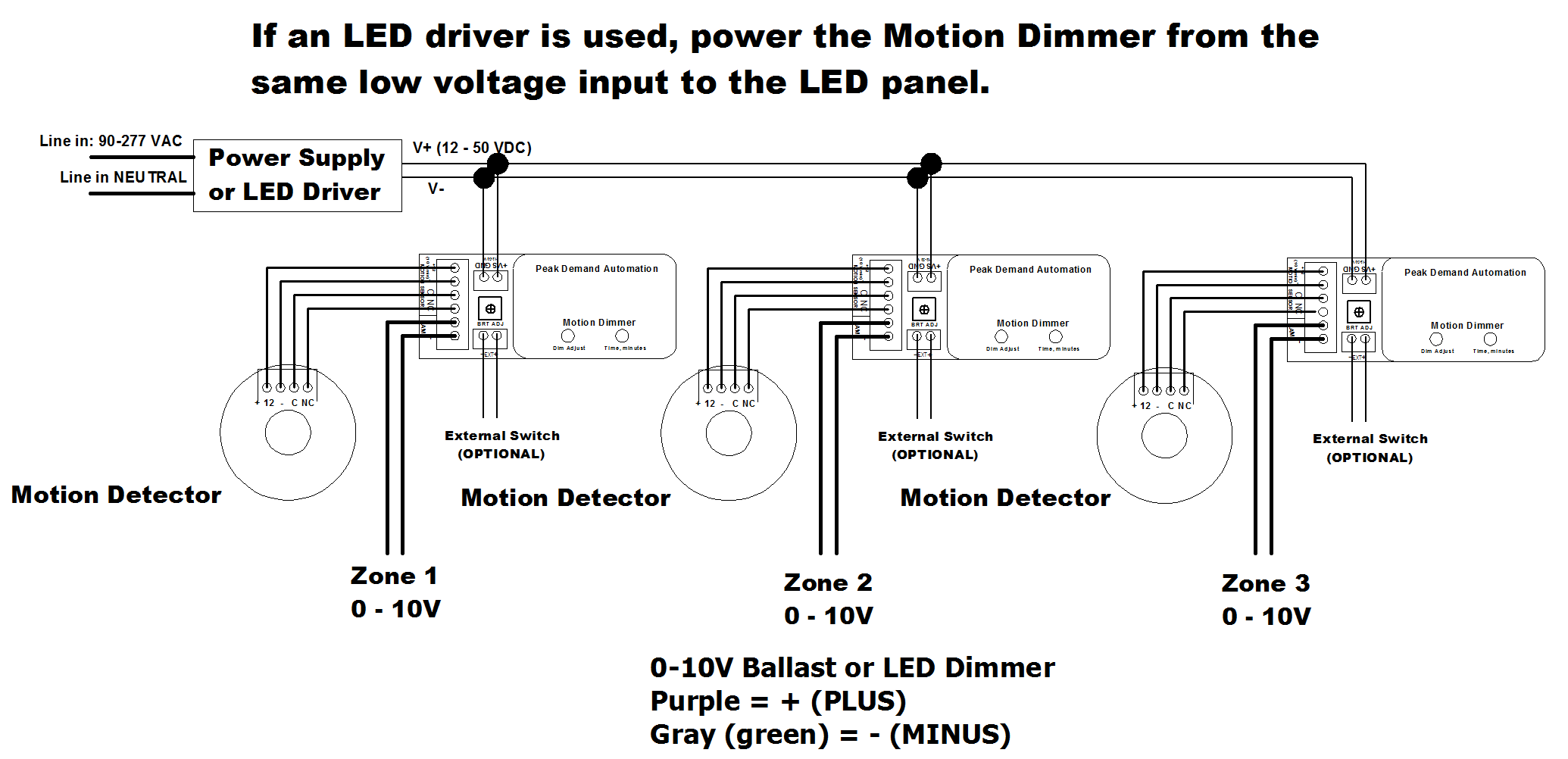
OSRAM . Connect wires per WIRING DIAGRAM as follows. V Preset Dimmer.
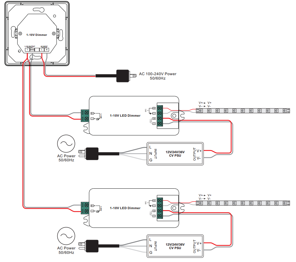
For use Advance Mark VII v Electronic Dimming Ballasts Wire controls according to the appropriate wiring diagram shown in. Determine locations to install the driver, fixture and control.
See ‘System Diagram. ‘ 3. Attach appropriate load and V control/dimmer to the driver.
See ‘Wiring.Preset Dimmer, LTMATE V volt low-voltage lighting control provides dimming control for volt compatible LED flat panel light, LED troffer, LED vapor tight, LED high bay, Linear, UFO by EATON Wiring. $ $ 38 59 Prime. FREE Shipping on eligible . V dimming wiring diagram V dimmer switch Leviton IPLFZ or equal For other types of dimming control systems, consult controls manufacturer for wiring instructions switched hot (black) switched hot (red typical) low voltage dimming wires (purple & gray typical) + Electrical Panel.
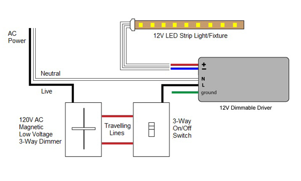
Wiring Guide Figure 1. Wiring in Control4 Panel Wiring Diagrams Use the Control4® 8-Channel V Dimmer wiring diagrams along with the 8-Channel V Dimmer Installation Guide to install 8-Channel V Dimmers.
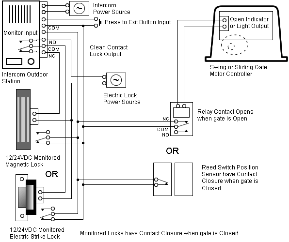
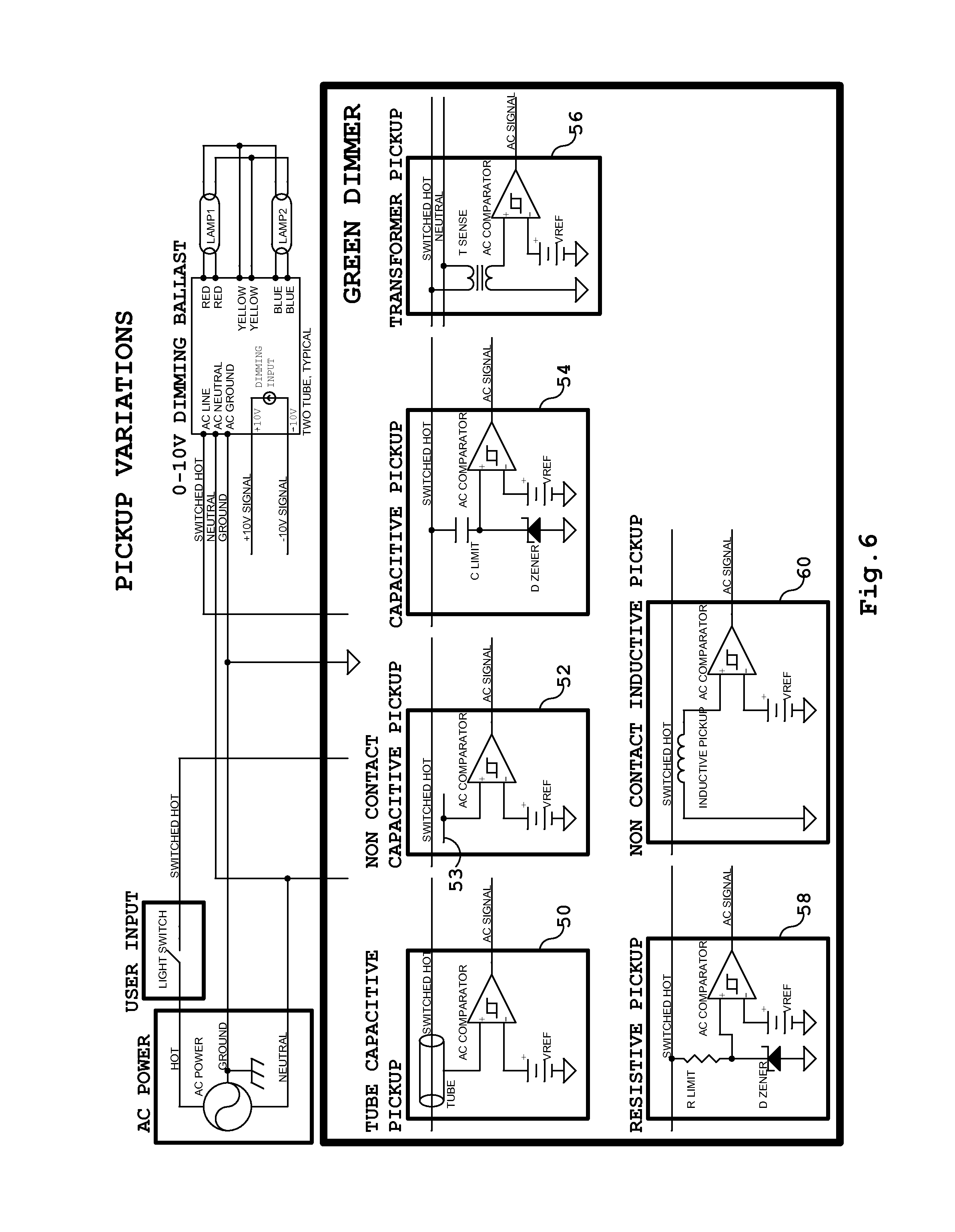
Diagrams Color Code: Black Line Red Switched Hot Grey Neutral Green Earth Ground Blue Ethernet Violet V (+). Advance Mark VII v Electronic Dimming Ballasts Dimming With ON/OFF Control Wiring Diagram Using Relay Figure C1: Dimming With ON/OFF Control Via Relay Connect the control as shown in Figure C2.
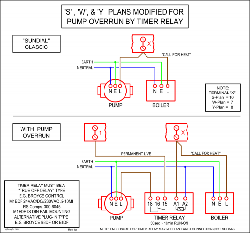
Do not install the Relay in the same wallbox as the low-voltage control. Refer to the wiring .
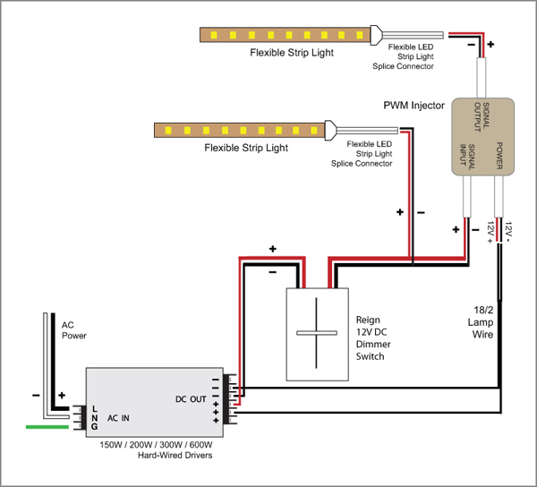
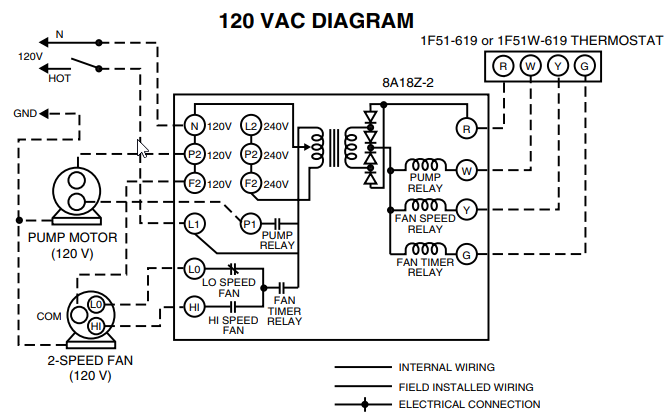
0 10v Dimmer Switch Wiring Diagram – A schematic shows contacts in a circuit in a pretentiousness that is positive and standardized. It is a pretension of communicating to extra engineers exactly what components are working in a circuit as capably as how they are connected.Lightology | What is V Dimming?schematron.org: Online Shopping for Electronics, Apparel, Computers, Books, DVDs & more
