
in a 2-wire (+10VDC and Common) bus connecting the controller to one or more LED drivers equipped with a VDC dimming input.
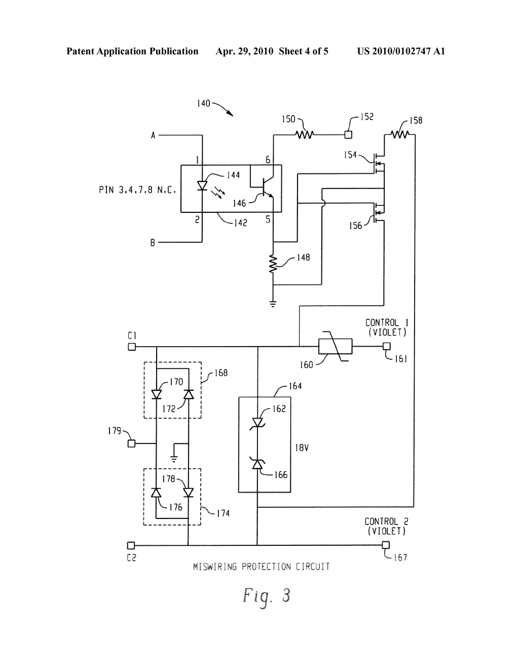
Pathway Connectivity. ground wire to make a secure connection to the safety ground of the electrical The Control4® V Dimmer operates independently or as part of a Control4.

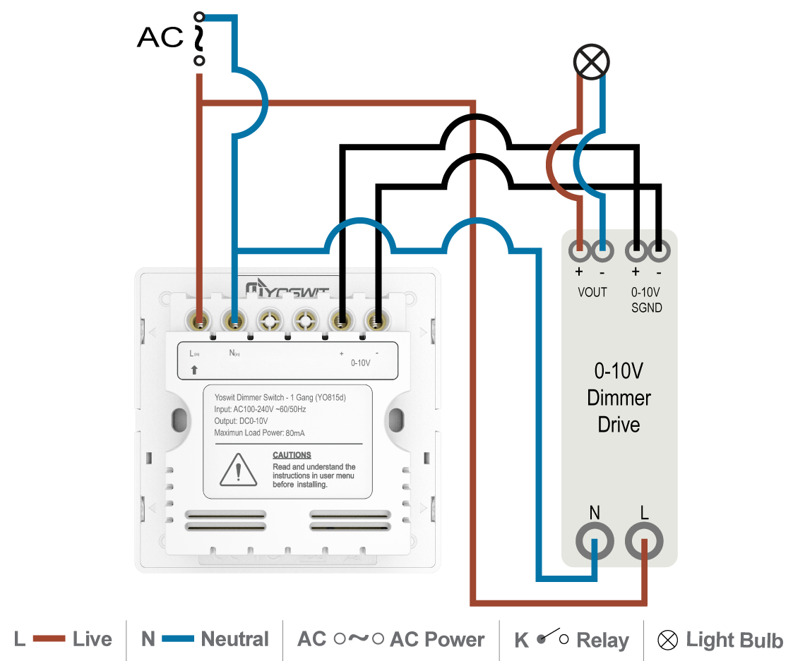
A V dimmer is considered analog dimming, and all USAI V dimming options are considered to be “sink” type dimming. A typical V wiring diagram is.
A common VDC wiring type is stranded-copper twisted-pair 18AWG wiring. The wiring is stranded copper because it provides a more stable current path (as .
A V dimmer is considered analog dimming, and all USAI V dimming options are considered to be “sink” type dimming. A typical V wiring diagram is.V dimming wiring diagram V dimmer switch Leviton IPLFZ or equal For other types of dimming control systems, consult controls manufacturer for wiring instructions switched hot (black) switched hot (red typical) low voltage dimming wires (purple & gray typical) + Electrical Panel hot (black typical) V or V, 60 Hz neutral (white.
A common VDC wiring type is stranded-copper twisted-pair 18AWG wiring. The wiring is stranded copper because it provides a more stable current path (as DC signals tend to be transferred by the outer edges of the conductor) while being relatively easy to work with; solid wire is usually acceptable in low-voltage systems that use AC control power.
Maestro 0–10 V Dimmer Sensor Maestro ® 0–10 V Dimmer Sensor Setting the new standard for 0–10V control W 0–10 V Dmi mer Sinking control for 0–10 V fluorescent and LED fixtures Passive Infrared (PIR) Sensor Fine motion detection with exclusive Lutron XCT TM technology. What is V Dimming?
Used as an early fluorescent dimming system and still used today, V dimming has been adapted to become a reliable LED dimming control protocol. V is one of the earliest and simplest electronic lighting control signaling systems; simply put, the control signal is a DC voltage that varies between zero and ten volts. V Class 1 and Class 2 Wiring Overview V ballasts and drivers are connected together by a 2-wire low voltage bus that is suitable for Class 1 or Class 2 wiring installations.

This application note explains how both Class 1 and 2 wiring are made and how .Low Voltage LED V Dimming | USAILightology | What is V Dimming?