Appendix: Wiring Diagrams. electronic fluorescent dimming ballast () and qualified for ISO . wires: Switched Hot, Neutral, VDC Positive, and.
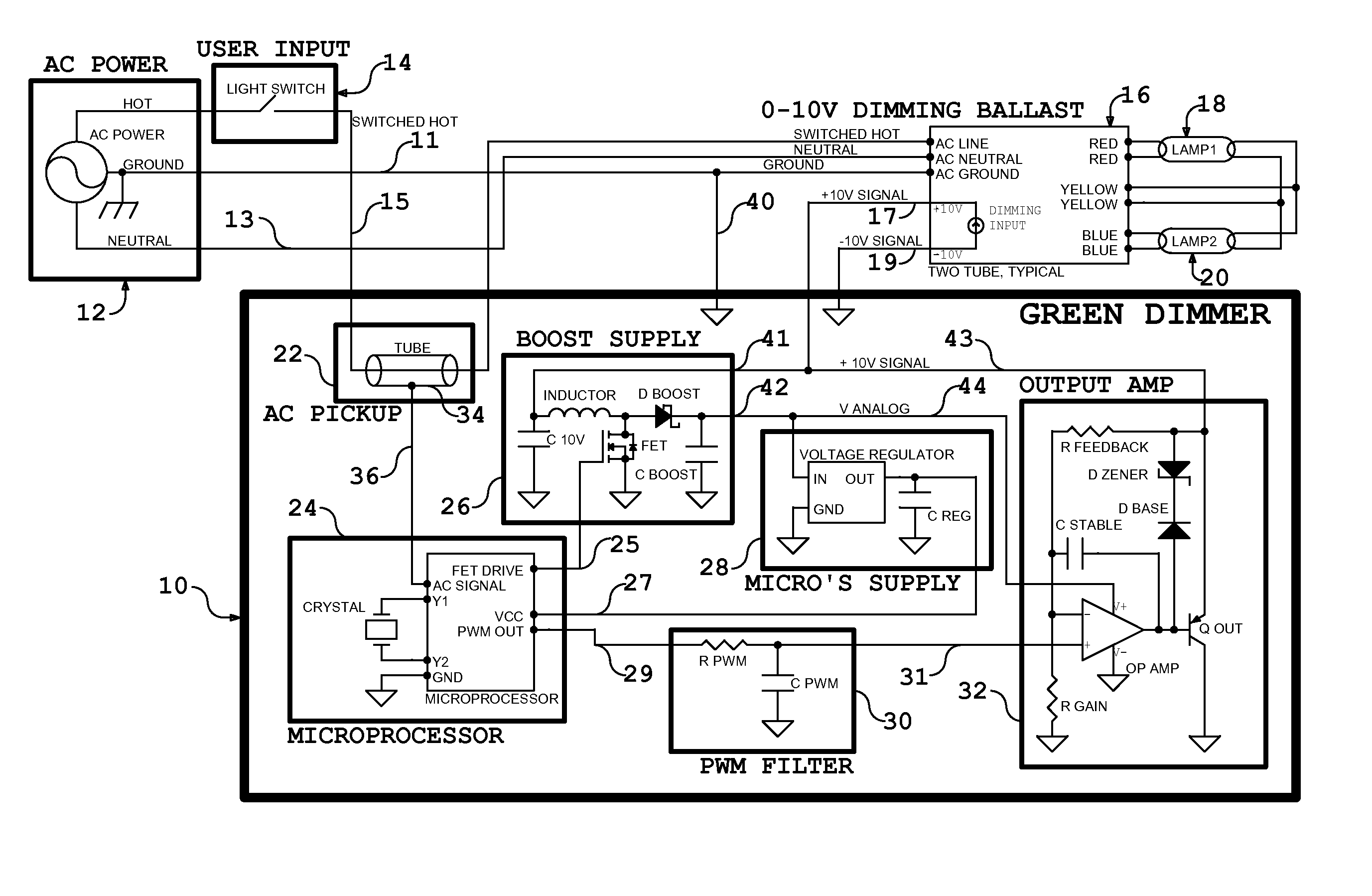
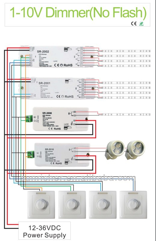
A V dimmer is considered analog dimming, and all USAI V dimming options are considered to be “sink” type dimming. A typical V wiring diagram is.
V Electronic Fluorescent Dimming Ballasts. Installation Wire controls according to the appropriate wiring diagram shown in the. “Wiring” section on pages.
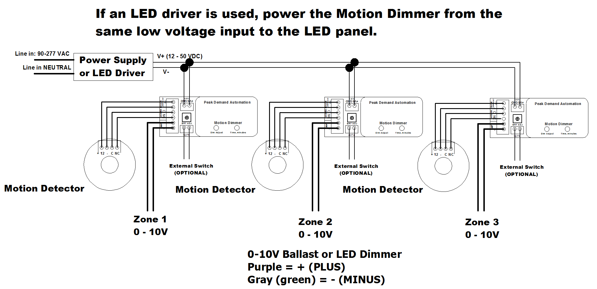
The Control4® V Dimmer operates independently or as part of a Control4 home automation V dimmable fluorescent ballasts and LEDs, sink or source. Identify your wiring application, and then see the appropriate wiring diagram.
Appendix: Wiring Diagrams. electronic fluorescent dimming ballast () and qualified for ISO . wires: Switched Hot, Neutral, VDC Positive, and.MARK 7 V ELE DIMMING BALLAST (2) F32T8 V – Philips Lighting.
Maximum dimming versatility | Philips Lighting. More brands from.
Philips Lighting. Lighting Electronics. Fluorescent.
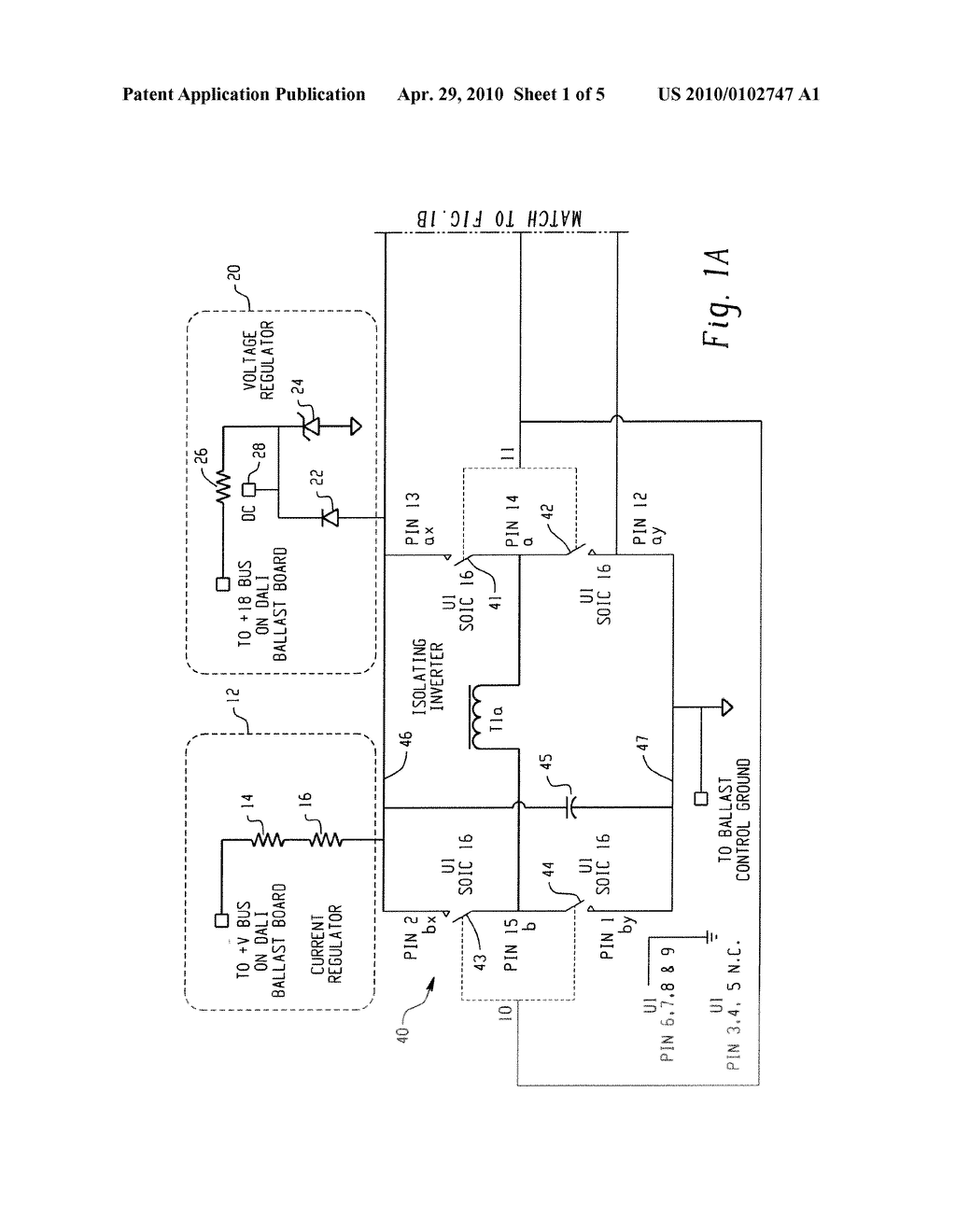
Max Ballast-Lamp Distance Tandem Wiring: Any = 6′ Max Ballast-Lamp Distance Through Wiring: Any = 6′. Wiring Diagrams Dimming With ON/OFF Control Wiring Diagram Using Relay V Ballast/Driver White White Red Red Red / White Blue Gray GrayGray Red Red Purple Purple Purple Blue White Black Black V Ballast/Driver Neutral Hot / Live / / / V~ 50 / 60 Hz PPH / H / H / H Class 2 Only Black Black Dimming With ON. V Class 1 and Class 2 Wiring Overview V ballasts and drivers are connected together by a 2-wire low voltage bus that is suitable for Class 1 or Class 2 wiring installations.
This application note explains how both Class 1 and 2 wiring are made and how . V dimming wiring diagram V dimmer switch Leviton IPLFZ or equal For other types of dimming control systems, consult controls manufacturer for wiring instructions switched hot (black) switched hot (red typical) low voltage dimming wires (purple & gray typical) + Electrical Panel hot (black typical) V or V, 60 Hz neutral (white.
ELECTRONIC DIMMING BALLASTS WITH ANALOG DIMMING CONTROL (V) FOR TWO (2) LAMP FIXTURES Cooper Controls Electronic Dimming Ballasts, powered by Fifth Light Technology, offer cost-effective, reliable dimming control for linear fluorescent lamps, down to .Lightology | What is V Dimming?MARK 7 V ELE DIMMING BALLAST (2) F32T8 V Mark 7 V – Philips Lighting
