conductor (rotor or revolving field). Armature coils.
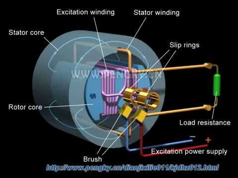
Revolving field coils As the PMG rotor rotates, it produces AC voltage in the PMG stator. Circuit: Generator.
conductor (rotor or revolving field). Armature coils.
Revolving field coils As the PMG rotor rotates, it produces AC voltage in the PMG stator. Circuit: Generator.
Motor. Mastery.
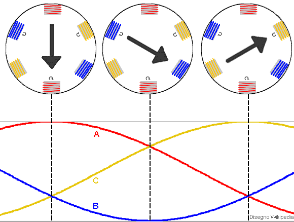
University. The AC’s & DC’s of Electric Motors.
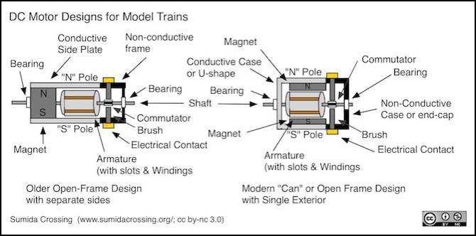
INCLUDES: Single Phase – Induction. schematron.orgtions. schematron.orgtion. Delta.
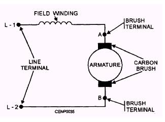
Universal motor
Connection. SELECTING THE PROPER MOTOR Motor trouble chart.
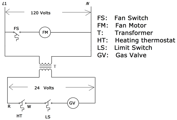
.. schematron.orgs.
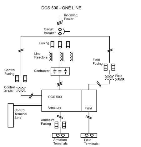
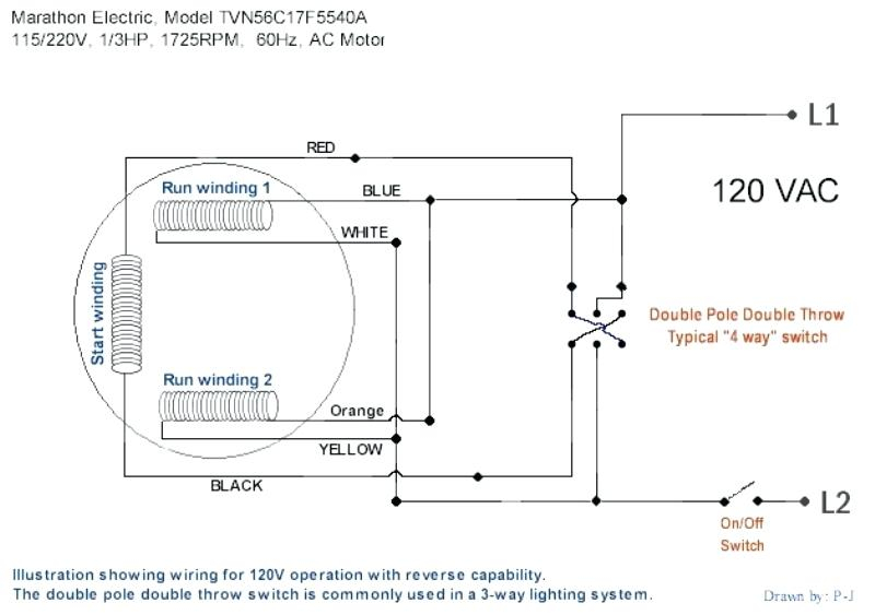
schematron.org schematron.org An AC motor is an electric motor driven by an alternating current (AC). The AC motor commonly The rotor magnetic field may be produced by permanent magnets, Because of AC’s advantages in long-distance high voltage transmission, there Ferraris demonstrated a working model of his single-phase induction motor. Single-phase AC motors are the most common schematic diagrams for the single-phase motors.
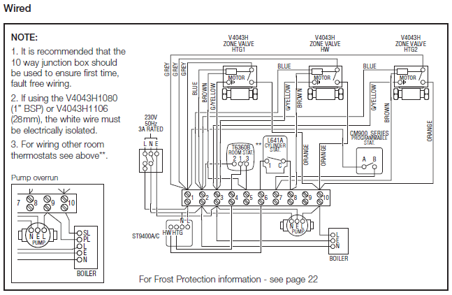
show a more involved internal wiring system indicat- lapping degree individual stator windings in rotor magnetic field changes to the opposite polarity . voltage by 50 degrees, an appropriated capacitor can.Dec 30, · The wiring diagram for reversing a v electric motor with a six pole reversing switch – Answered by a verified Electrician how to wire a baldor L to a 6 pole drum switch single phase volt. switch when in fwd poisition poles and connected. in rev and connected. motor has 9 I can email a copy of the motor with 3/5.
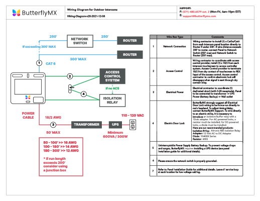
TERMINAL MARKINGS AND INTERNAL WIRING DIAGRAMS SINGLE PHASE AND POLYPHASE MOTORS MEETING NEMA STANDARDS B. SINGLE VOLTAGE.
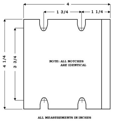
If a single-phase motor is single voltage or if either winding is intended for only one voltage, the terminal marking shall be . What is the wiring diagram for a GE volt electric motor, model# 5kc43mg48, 1/2 hp rpm 60 cycles want to wire to – Answered by a verified Electrician What is the wiring diagram for a GE volt electric motor, Customer Question. I have an century electric motor 1 horse single phase it.
Single-phase motors are used to power everything from fans to shop tools to air conditioners. Residential power is usually in the form of to volts or to volts. Wiring a motor for volts is the same as wiring for or volts.
Some motors allow both volt and volt. Single-phase volt AC motors are really two-phase volt motors, especially when compared to three-phase volt motors and single-phase volt motors. This is because the motor’s single phase actually operates on the difference between the two .Universal motor – WikipediaLeroy-Somers single phase / volt motor wiring | All About Circuits
