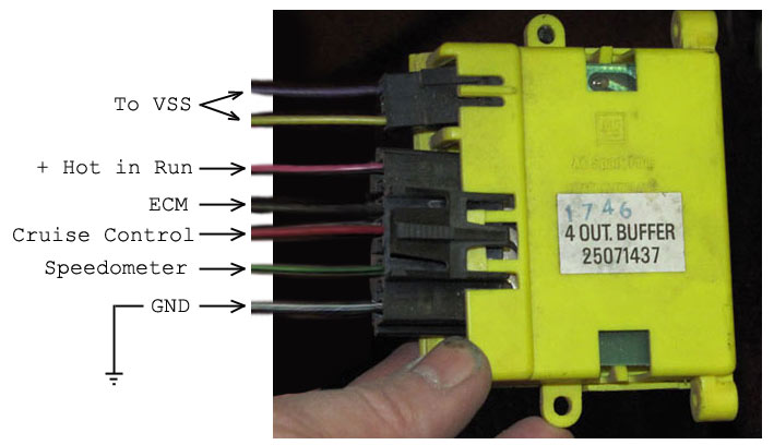
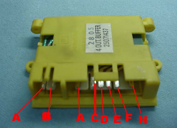
Get free help, tips & support from top experts on chevy vss buffer related issues. VSS) and vehicle speed signal buffer wiring diagram REMOVAL & INSTALLATION See Figure 2 Disconnect the negative battery Chevy TBI All 89 parts to include wiring harness and steering column.

One says yellow wire from vss to speedo, but then I read that there is a buffer box the vss goes through From to they had a separate DRAC module outside of the cluster C12 – Vehicle speed sensor input – purple with white tracer. I have a chevy astro van awd with a L, the vehicle will not shift out of 1st I have seen the speed sensor buffer or a broken wire cause this problem before.
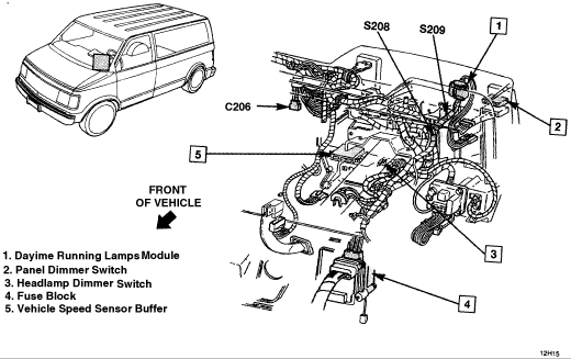
Neither have the same color coded wires as the diagram that was given to me. . Chevy Astro W ok, I was not getting fuel to the motor, turns out it was.
Get free help, tips & support from top experts on chevy vss buffer related issues. VSS) and vehicle speed signal buffer wiring diagram REMOVAL & INSTALLATION See Figure 2 Disconnect the negative battery Chevy TBI Computer problem Chevy Van Two Wheel Drive Automatic Purple/White and Light Green/Black wires of VSS buffer connector.Chevy Van Two Wheel Drive Automatic miles I have a 95 G20 Chevy van: ABS light stays on, Speedometer does not function, will not shift out of first.
The Speed Sensor has been replaced, VSS buffer has been tested good, instrument cluster has been tested good. All wiring seems good.

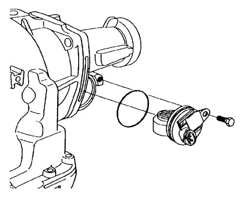
Fig. Fig. 1: Vehicle Speed Sensor (VSS) and vehicle speed signal buffer wiring diagram To test the VSS, backprobe the VSS terminals with a high impedance voltmeter (set at the AC voltage scale).
Safely raise and support the entire vehicle using jackstands. Two things it could be: speed sensor buffer like mentioned, or wiring.
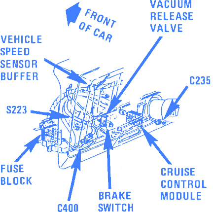
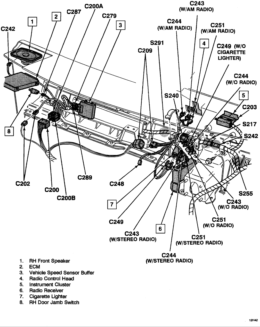
The buffer is located behind the passenger side dash, behind the glove box, usually next to or underneath the ECM (main engine computer). The buffer, takes in the speed sensor signal and converts it to a usable signal, and distributes it to the ECM, Cruise Control, ABS.
Diagnosing GM DRAC and Speed Sensor Circuits 4 GEARS April I f you have a to We’re going to look at a C Chevrolet pickup truck with a L engine and a 4L60E transmission. location. Some PCM pin locations and wire colors vary, so consult a wiring diagram and an electrical component location chart for the.
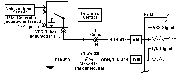
The external VSSB/DRAC module was used in TBI Gas Chevy and GMC Vehicles in many applications. The external VSSB/DRAC module was also used in applications from in Chevy and GMC L and L DIESEL applications.Chevy Van 95 G20 Chevy Van: ABS Light Stays On, SpeedoUD: GM DRAC Module GM VSSB Module Replacement and Speedo Calibration TBI VSSB Speedometer Buffer
