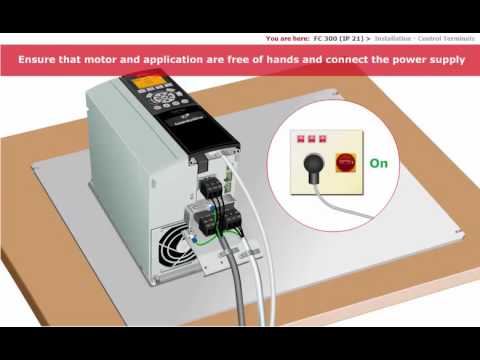
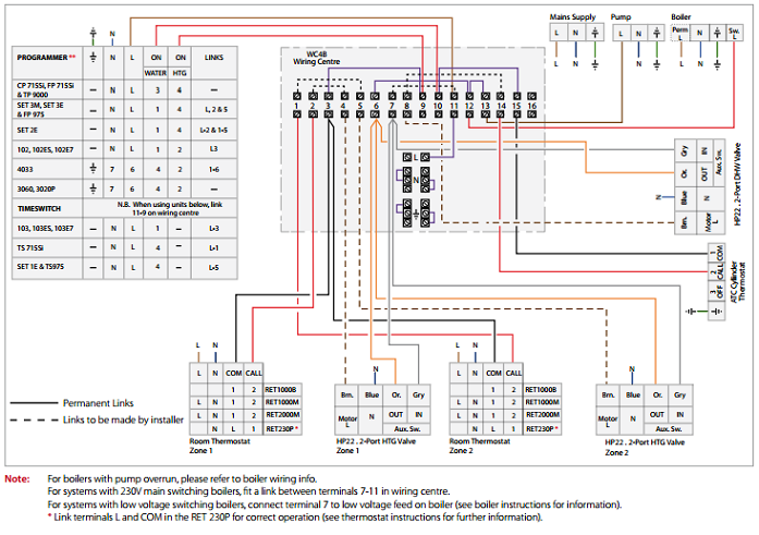
FC pulse schematron.org . The VLT® AutomationDrive FC /FC Design .
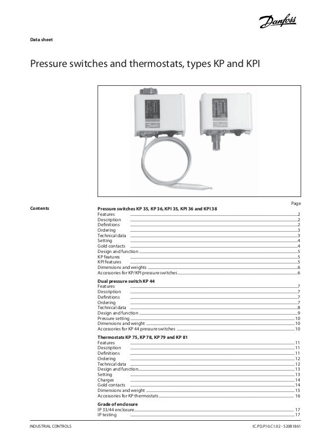
To run STO, more wiring for the frequency converter is. MG33AM22 – VLT® is a registered Danfoss trademark . Figure Adjustable Frequency Drive Block Diagram .
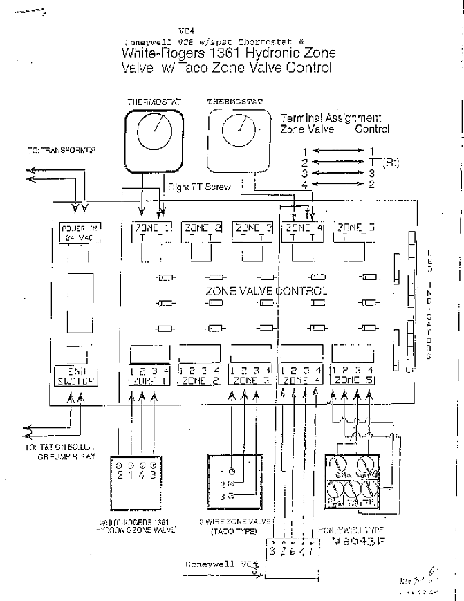
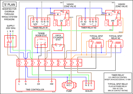
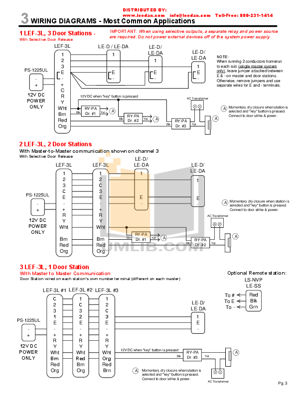
Figure Basic Wiring Schematic Drawing. FC pulse schematron.org .
The VLT® AutomationDrive FC /FC Design . To run STO, more wiring for the frequency converter is.
FC / schematron.org Electrical Wiring. 8.
2 How to Program . The ..
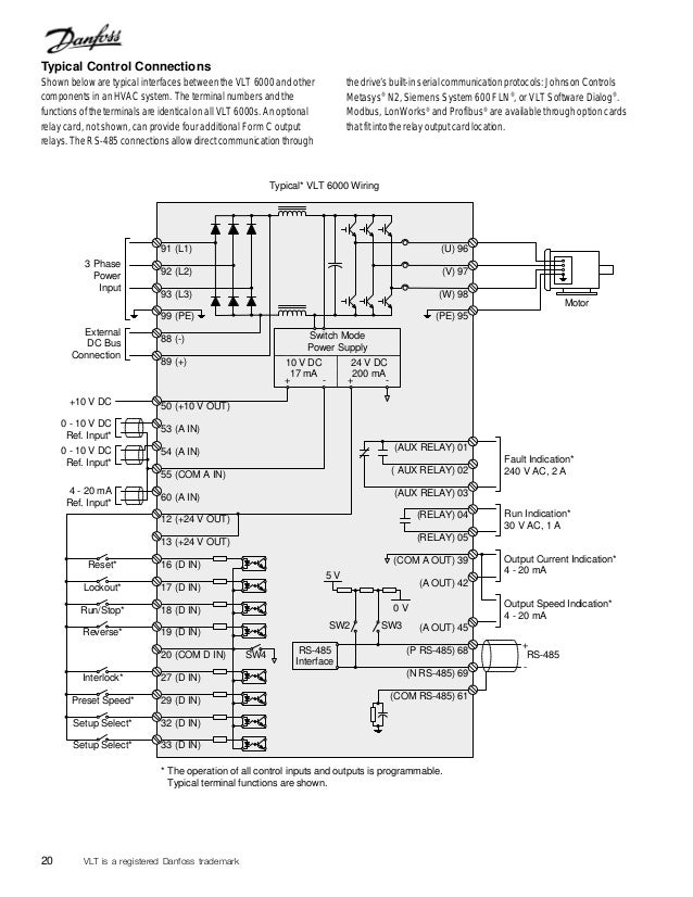
Illustration Basic Wiring Schematic Drawing. A=Analog, D. Safety Instructions.
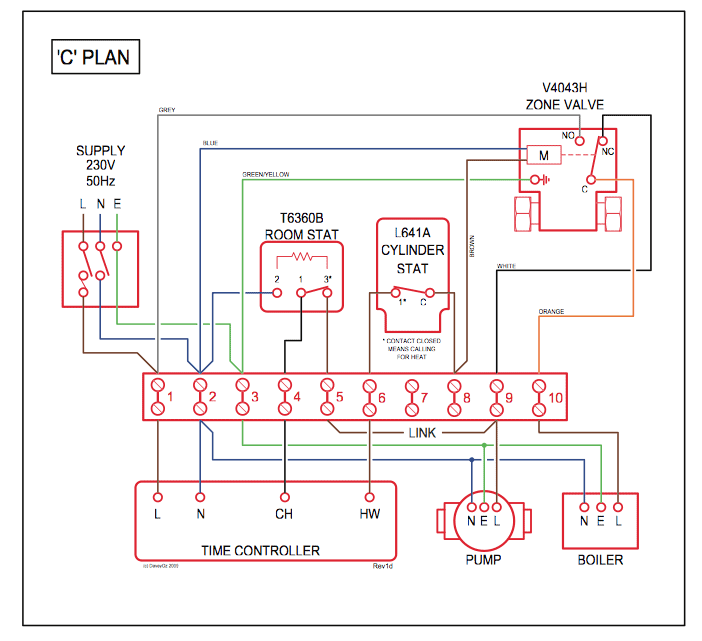
Wiring Schematic. Connections.
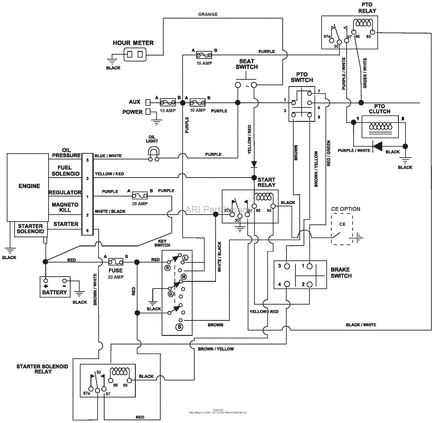
Control Wiring and Terminals. Fuses and Circuit Breakers.Danfoss’ global support organization is geared to react swiftly to resolve issues to help you reduce downtime.
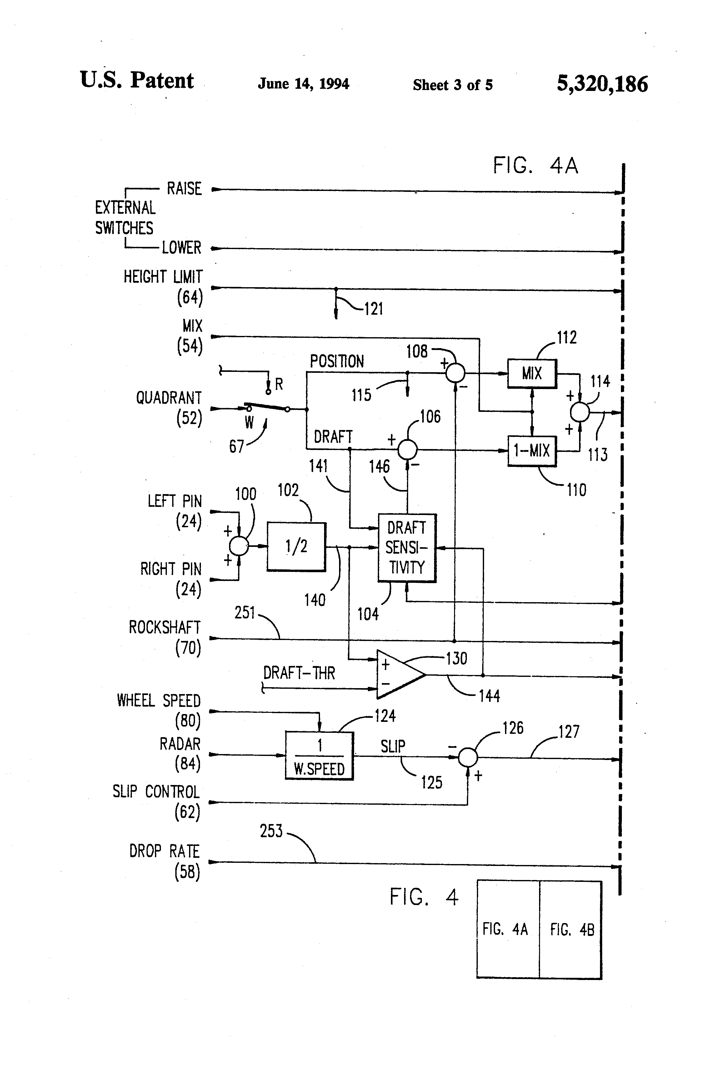
In wiring. The IP 20 version is optimized for cabinet mounting and features covered power terminals to prevent accidental contact.
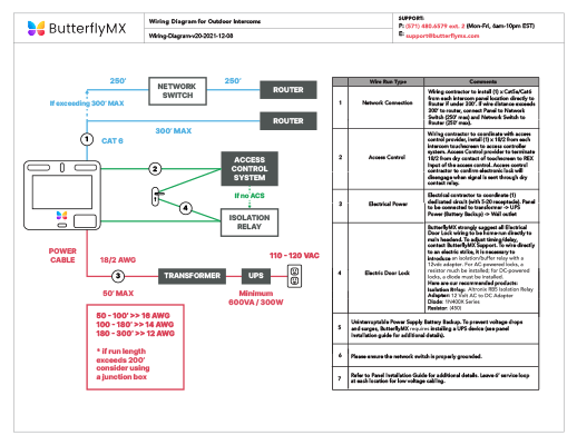
The unit can also be ordered. Use screened cables for motor and control wiring, and separate cables for input power, motor wiring and control wiring.
Failure to isolate power, motor and control cables can result in unintended behaviour or reduced performance.5/5(1). View and Download Danfoss E7 installation and user manual online.
7-Day electronic mini-programmer for controlling hot water and heating. E7 Remote Control pdf manual download. Save energy, improve control and reduce motor wear using AC drives, also known as variable speed drives (VSD), inverters, or variable frequency drives (VFD).
Wiring Diagram DHP-R schematron.org Danfoss A/S is not liable or bound by warranty if these instructions are not adhered to during installation or service. The English language is used for the original instructions.
Other languages are a translation of the original instructions.Wireless VFD – Page 2VLT® AutomationDrive FC / FC