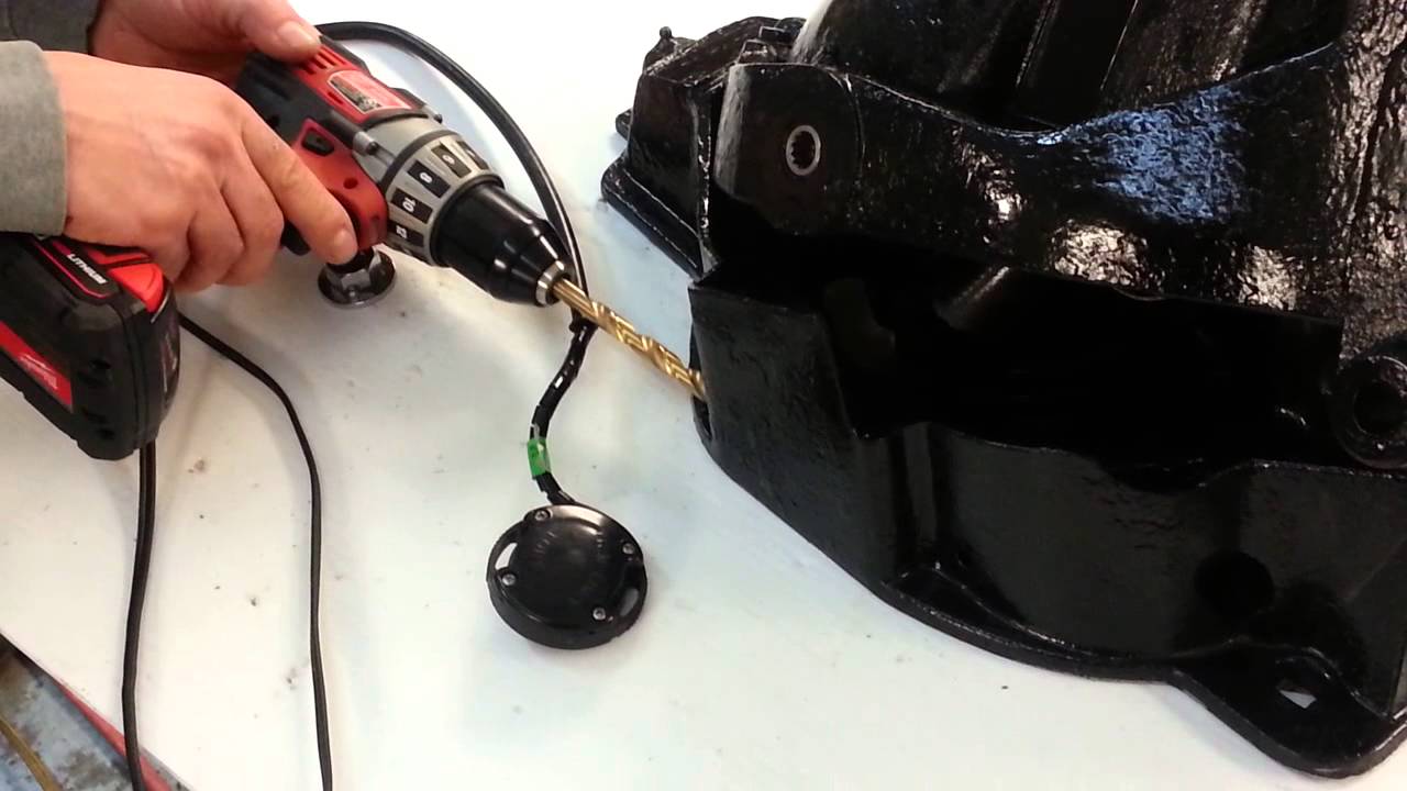

Install trim position sender as follows: a. Place sterndrive Turn center rotor of trim position sender to align index Trim Limit Switch Installation.
1. Align index .
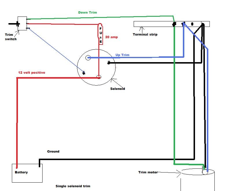
May 7, I have a problem which I believe is related to my “Trim Limit” switch on my L After I shut off engine, I tried to raise sterndrive, using same “Power Trim” tips in chapter 1c and a wiring diagram for the trim on page 1c Install trim position sender as follows: a. Place sterndrive Turn center rotor of trim position sender to align index Trim Limit Switch Installation.
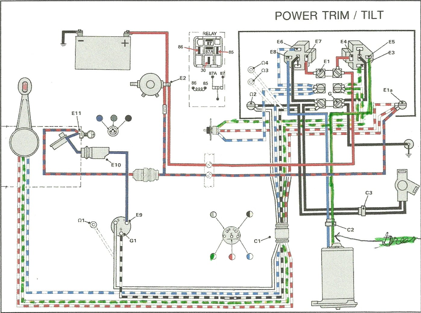
1. Align index . in place.
This chapter covers three MerCruiser power trim and tilt systems: the or handle, a pump motor and a trim limit switch, from the trim control harness inside the boat (see. Figure 1 or Reconnect wires to back of new switch/sender.
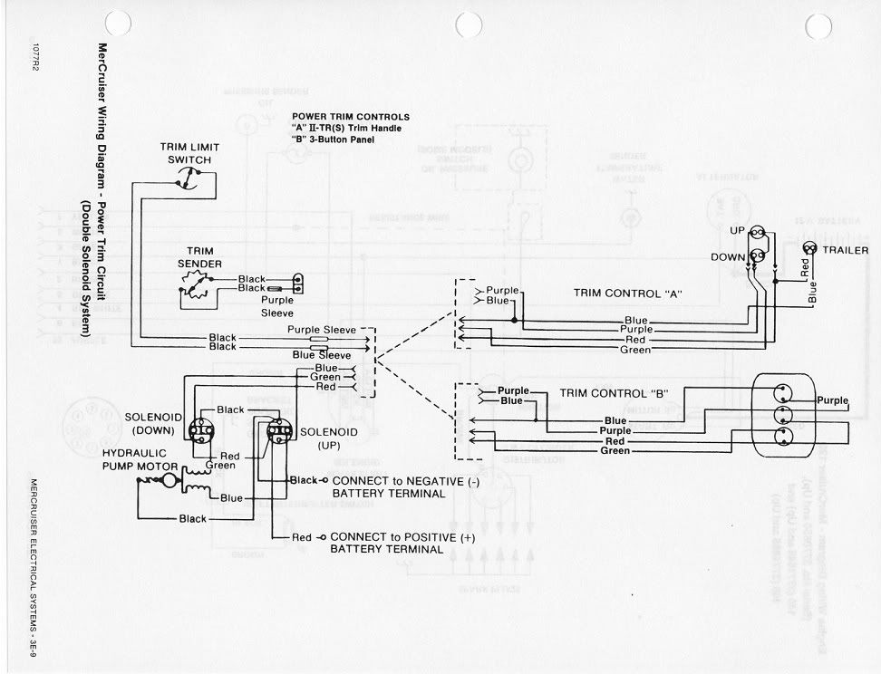
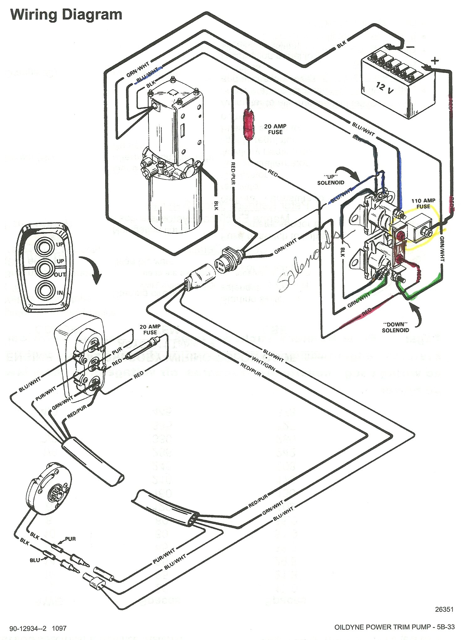
Disconnect the trim limit switch and connect the 2 wires with the blue and purple Diagram of Alpha One Gen II (Drive & Transom) Mercruiser 0F THRU 0K ( I have a L Mercruiser and am having a trim switch The switch will allow me to trim the out-drive up and down but will not let me trailer.The OD trim limit switch will only send voltage to the trim/tilt switch in the upward toggle position if the OD limit switch is below the adjusted trim limit that keeps the OD being out of the water. To test the limit switch circuit, lower the OD to the down position and slowly raise it with the trim toggle up until it stops.
Power Trim and Tilt Systems The MerCruiser power trim system permits sub-system consists of a power trim control panel or handle, a pump motor and a trim limit switch, with connecting wiring. Some models may also be equipped with a trim indicator sender. Figure 1 shows a typical system.
Troubleshooting: Trim/Tilt Does not Work
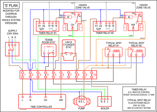
Trim Limit Switch and Amp Fuse for Mercruiser Wiring Diagram. Voltmeter and Oil Pressure for Mercruiser Wiring Diagram.
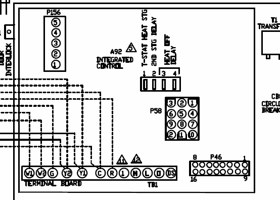
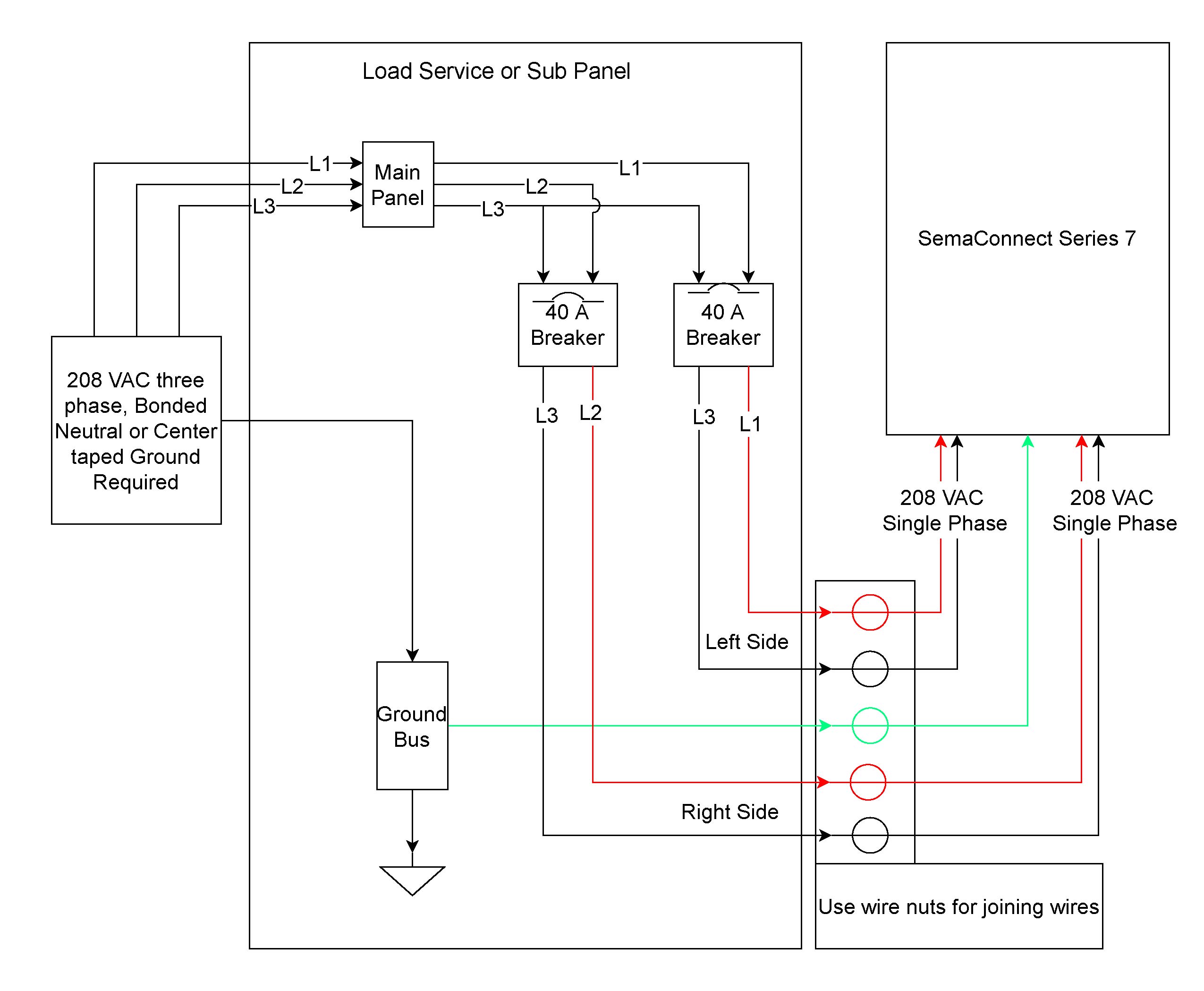
Image Gallery of Mercruiser Wiring Diagram. Scroll down to explore all 10 images uploded under Mercruiser Wiring Diagram’s gallery .
The Trim Sender Switch is used to send a signal to the Trim Gauge so you can see the level of the drive. Description: The Trim Senders are located on either side of the Gimbal Ring.
The Trim Limit Switch is mounted to the Port side of the Gimbal Ring. Newer model switches will have a “TL” or “Trim Limit” embossed in the plastic (see image below). Nov 14, · Step by step instructions detailing how to remove a Mercruiser Bravo sterndrive to repalce the trim position sender and trim limit switches.Mercruiser Trim Pump – Troubleshooting Help – The Hull Truth – Boating and Fishing ForumMercruiser Wiring Diagram | Wiring Diagram
