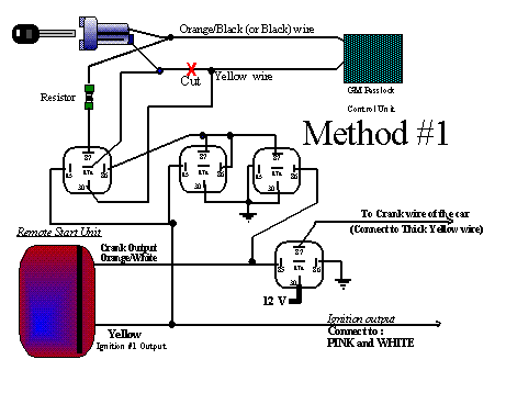
Resistance Code section of this manual.) Passlock I Wiring Diagram.
Harness 1. 1 GREEN/BLACK.
(+) Starter (from vehicle). 2 BLACK/WHITE.
Bulb check. 2.
PASSLOCK I INSTALLATION. NOTE: Never connect the wiring on the Passkey or Passlock system without first setting the dipswitch .
WIRING DIAGRAM. Passlock ll also uses a R-Code, but rather than going through the PASSLOCK I WIRING DIAGRAM 2-Pin Connector for the On-Board Ignition Two Relay.
Resistance Code section of this manual.) Passlock I Wiring Diagram. Harness 1.
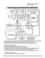
1 GREEN/BLACK. (+) Starter (from vehicle).
2 BLACK/WHITE. Bulb check.
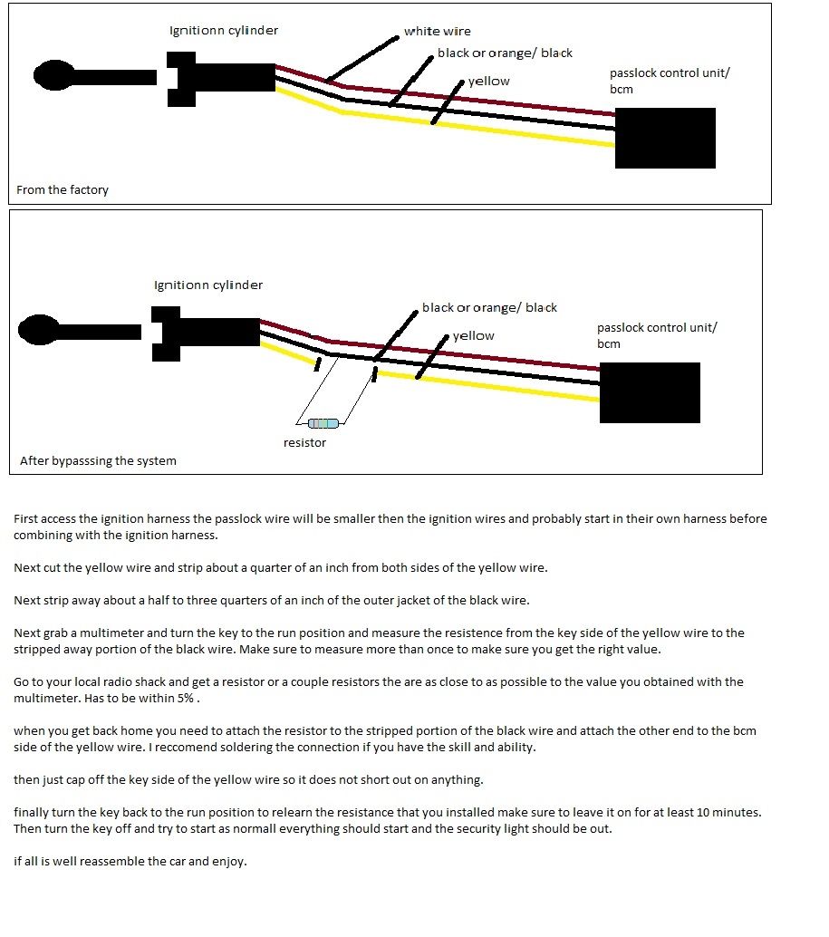
Resistance Code section of this manual.) Passlock I Wiring Diagram. Harness 1.
1 GREEN/BLACK. (+) Starter (from vehicle). 2 BLACK/WHITE.
Bulb check.Passlock 2 wiring diagram together with 97 blazer ignition switch wiring diagram along with 3lzzz location pass key module 95 grand prix gt together with chevy cavalier crank sensor location together with 97 buick lesabre vats wiring diagram as well as olds alero charging system wiring diagram also how to replace the ignition switch in a chevy impala together with 97 pontiac grand am. Passlock 2 bypass without module!
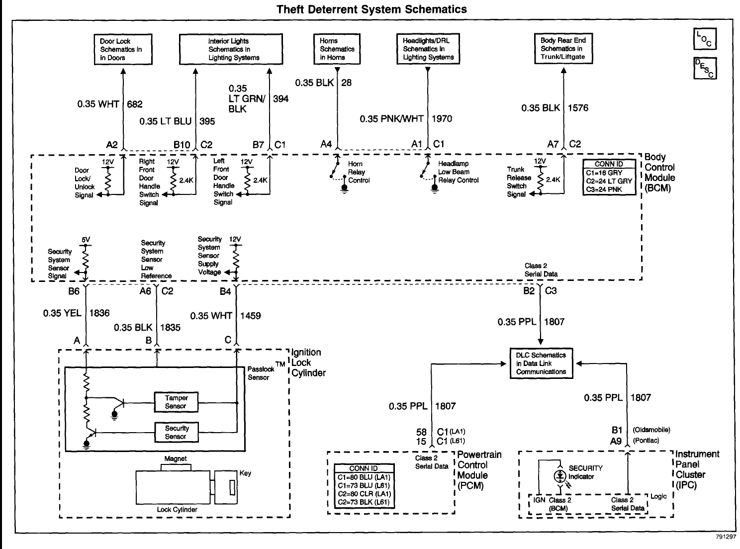
– All passlock 2 system can be bypassed with 2 diodes. Cheap, easy and works all the time!Here’s how to do it. You can use a relay if you dont want to lose your passlock 2 permanentl.
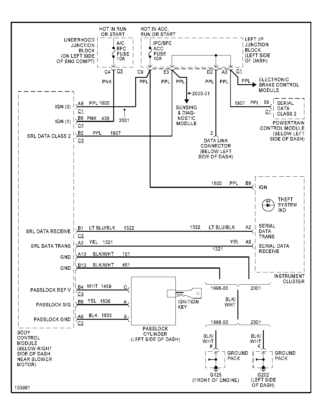
PASSLOCK 2 wire Diagram for 8-Pin Harness on IF Bypass Module: This is a Diagram for PASSLOCK 2 when connecting the IF Bypass Module, when using this diagram, the wires marked in. Listed below are a number of top notch gm passlock wiring diagram photos on internet.
We found it from reliable resource. Its posted by Ella Brouillard in the best field.
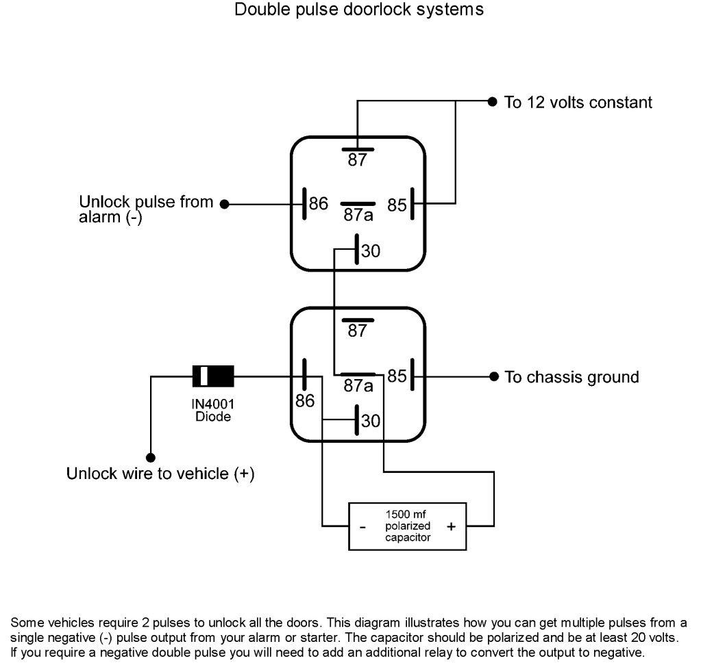
We expect this gm passlock wiring diagram photo can be the most trending niche once we distribute it in google plus or twitter. This is a BASIC Installtion Diagram used when Installing the Bypass Module to GM’s PASSLOCK2 Anti-then System. The wires that are needed for this Installation are marked in in this diagram, all others to be taped up and do not use.
RED RED to 12 Volts Constant fused at 3 Amps ORANGE to PASSLOCK 2 wire that tests (-)Negative or Ground.GM Passlock Security FixGm Passlock 2 Wiring Diagram – schematron.org