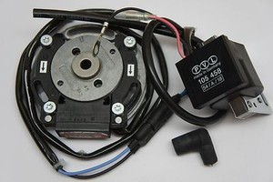
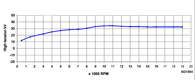
, black, analogue, without regulator/CDI, – windings, Kart/ Motorbike, Moto 4 is a AMP Superseal plug connector, 5 is a double plug connector PVL Please take the ignition curves from the Diagrams.
The ignition coil must be secured during installation so that vibrations during driving do. PVL IGNITION INSTALLATION &.
OPERATING INSTRUCTIONS. COMPONENTS INCLUDED IN THIS KIT: Rotor. Stator (Windings/Legs attached to Stator Plate).
Connect the ignition switch (red connection) and, at the ignitions with two ignition curves, the ignition curve Max advance the PVL ignition advance curves according to diagram In analog systems such as or is the max. Casing numbering: You will find both ignition curves on the Diagram Pages/a> for comparison.
The ignition Plug connector: PVL plug connector (5). , black, analog, ohne Regul/CDI, – trns. have to replace the blade terminal and the black wire to the blue wire and the blue wire to the black.If e.g.
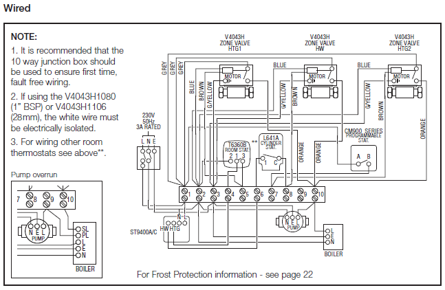
stator is combined with plug connector type 2 (flat plug connector) and rotor with ignition coil , the standard direction of rotation is clockwise and the plug connector is coil start “blue” and coil end “black and white”. If you wish to change this ignition to anticlockwise, only the flat plug connectors need to be.
Welcome to Tal-Ko Racing, the UK’s largest manufacturer of engines for kart racing and a leader within the sport of karting for over 50 years. For example, the stator combined with connector type 2 (flat connector) and the rotor with ignition coil , the rotation is by default right-handed, and the connector is turning start “blue” and turning end “black “.
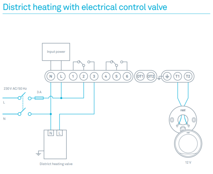
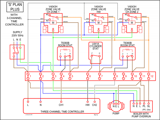
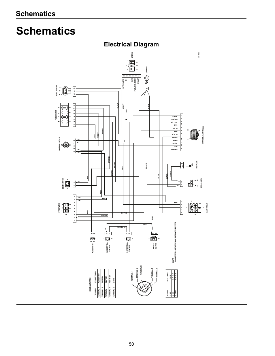
Wiring diagram; Stator und Rotor einbauen; Setting the Ignition timing; Testing of the PVL ignition. Some of the PVL components can be subjected to a resistance test.
A digital ohmmeter should be used to check PVL ignition components. , 4,8k Ohm – 5,1k Ohm.
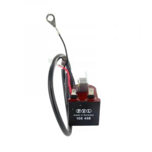
Description PVL analog Coil / , analog coil, black, plug in typ 2.PVL ignitions – infinitely programmable digital ignitionsIgnition Coil Analog Types