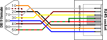
Pinout of PC serial port (RS DE9) and layout of 9 pin D-SUB male connector and 10 pin IDC male connectorThis RSC DE-9 (usually. Pinout of Null modem cables and layout of 9 pin D-SUB female Use this cable to connect two devices equipped with serial RS interface.
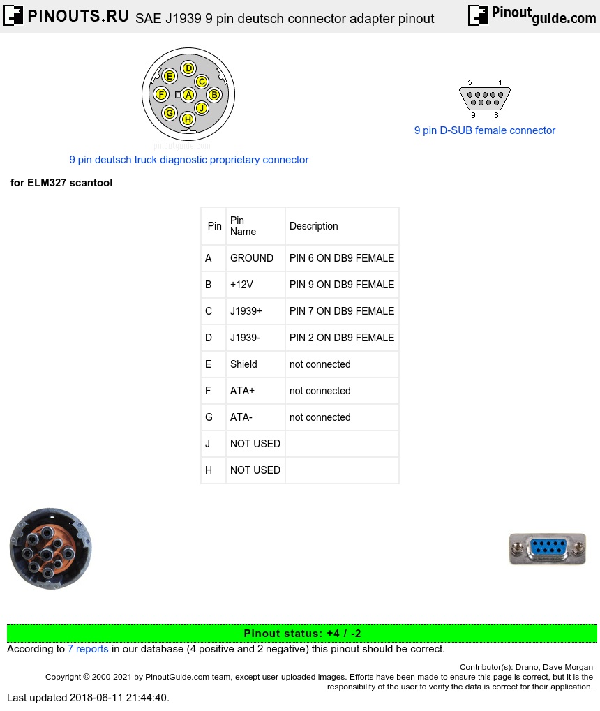
RS pinout for standard serial DB9 pinout serial connector. How should cables between different types of RS ports be wired? a male DB25 or possibly a male DB9 connector and a DCE will have a female DB25 or DB9. The most common pinout for DB9 serial connectors is.
RS serial cables and adapters. Pinout and wiring layout for many situations.
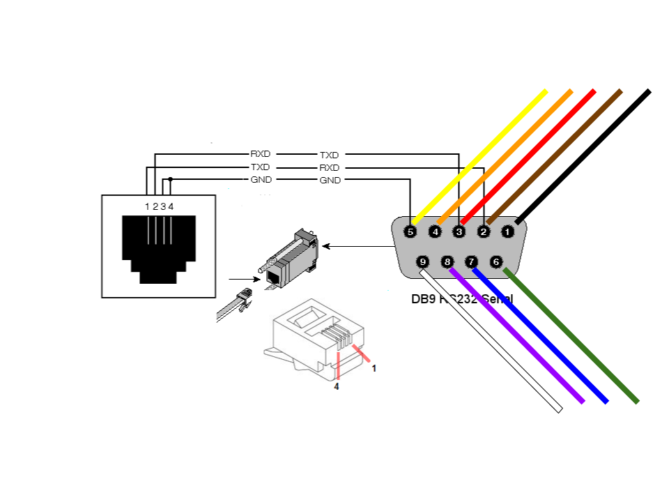
DB9 to DB25 conversion and null modem wiring diagrams.RS Wiring Diagrams. The unfortunate thing about RS is that aside from the simplest TD to RD and SG to SG hookups, and computer to modems (essentially straight through because a modem is DCE- just the reverse of a computer), everybody does it differently.
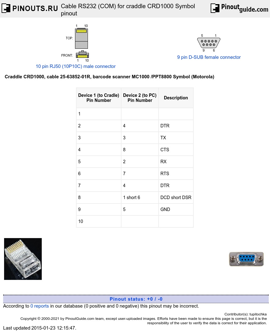
RS Wiring. Using the CPU 9-pin Serial Port.
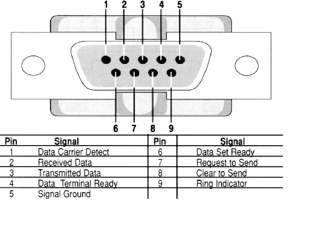
The RMC CPU module has a DTE DB9 serial port labeled “RS Monitor.” Both RMCWin and the RMCLink ActiveX Control schematron.org Assembly Component use this port. RS DB25 to DB9 converter The original pinout for RS was developed for a 25 pins sub D connector.
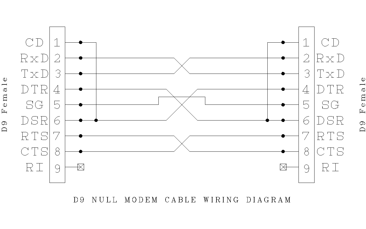
Since the introduction of the smaller serial port on the IBM-AT, 9 . RS Wiring.
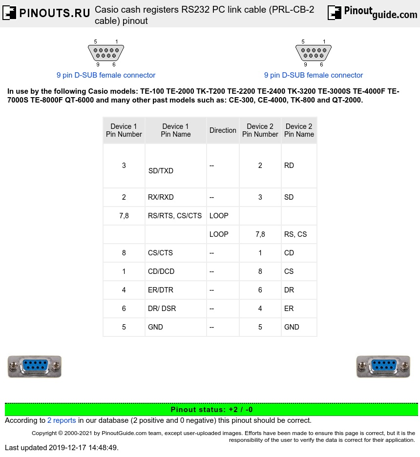
Using the CPU 9-pin Serial Port. The RMC CPU module has a DTE DB9 serial port labeled “RS Monitor.” Both RMCWin and the RMCLink ActiveX Control schematron.org Assembly Component use this port.
RS pinout RS pinout standards exist for both DB9 and DB25 connectors as shown below: DB25 SIGNAL DB9 DEFINITION 1.RS DB9 pinout diagram @ schematron.orgRS serial cable pinout information