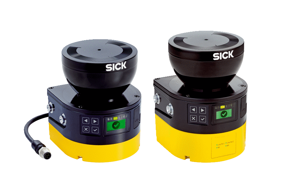
Integrating the equipment into the electrical control. The operating instructions apply to the microScan3 safety laser scanner with the follow‐ .

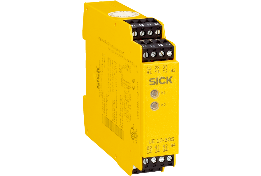
analyze the signals (for example using a safe control or safety relays) and stop the dan‐. MICS3-AAAZ55AZ1P01 | microScan3 Core . Connection diagram Core I/O with restart interlock and external device monitoring at UEFG safety relay.
Ideal for the connection of emergency stop pushbuttons and safety switches; 3 safety outputs, 1 application diagnostic output; Manual or automated reset. Described product. microScan3.

Manufacturer. SICK AG. Erwin-Sick-Str. 1 ..
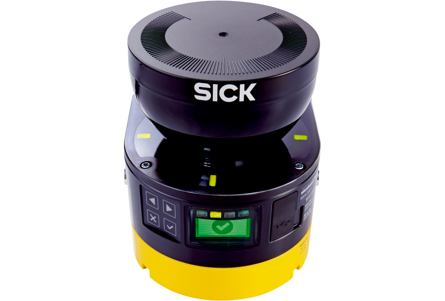
Integration in the electrical control. Operating instructions of the safety laser scanner must be made available to all people who work .
analyze the signals ( for example using a safe control or safety relays) and stop the dan‐. SICK has combined its extensive knowledge, considerable experience, and power Uncomplicated mounting: No special installation preparations are required for the system . The microScan3 is the first safety laser scanner to reach .
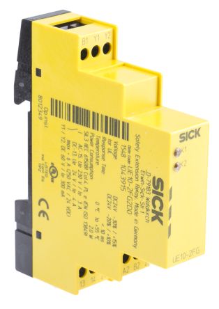
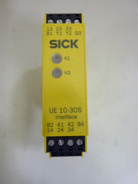
cal data, CAD design models, operating instructions, software, application examples.Safety relays Safety relays SICK’s wide range of safety solutions – from single-channel emergency stop pushbuttons to safety laser scanners with PNP outputs – can be connected us-ing SICK safety relays. Safety relays are ideal for flexible, cost-effective machine integration. With SICK’s broad safety.
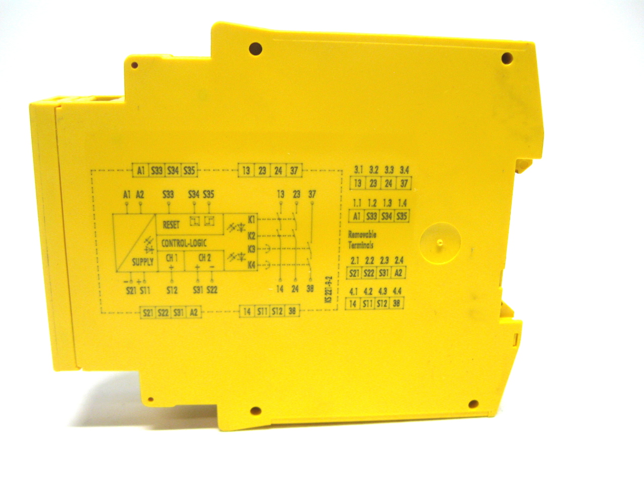
Rockwell Automation Publication SAFETY-WDK-EN-P – March 3 Next Generation Guardmaster Safety Relay (GSR) Notes for Example Wiring Diagrams Note 1 In the wiring diagrams that are shown in this publication, the type of Allen-Bradley® Guardmaster® device is shown as an example to illustrate the circuit principle. Connection examples * ˘ 6 Performance_Level: e to DIN EN ISO S IL 3 to D NE Category 4 to EN We reserve the right to make alterations without prior notice ifm schematron.org Date: page 1 of 15 Connection examples for wiring the safety relay GS.
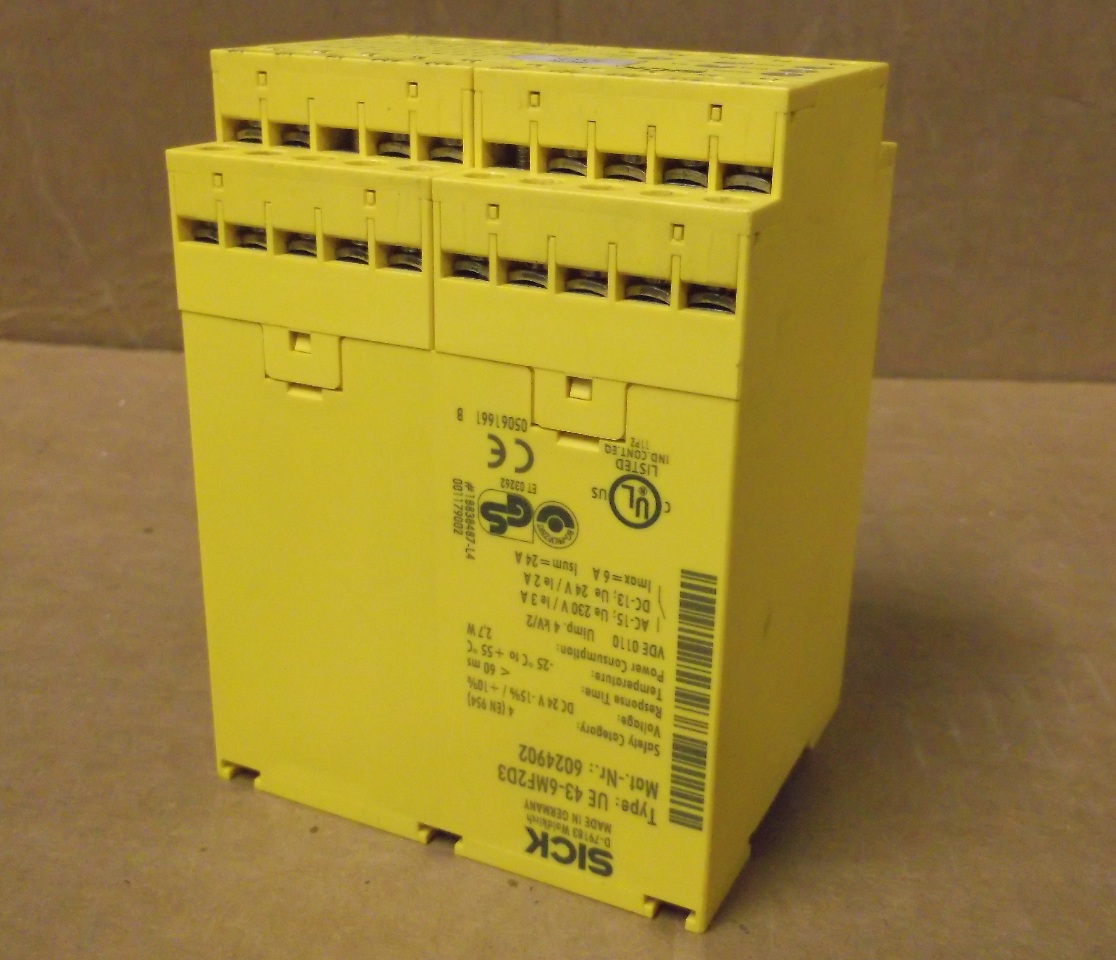
Safety Relays 3 A safety relay: •Is designed with an internal circuit that will allow power to be Wiring Diagram and logic circuit for ZBR And ZBRFigure 5 Safety Relay Operating Principle. 50 msec Max Legend 0 1 8 Safety Relays E–Stop Open All relays are de–energized.
Connection diagram microScan3 Core I/O with restart interlock and external device monitoring at UEFG safety relay. Connection diagram microScan3 Core I/O with restart interlock and external device monitoring.

Opto-electronic protective devices. Photoelectric .Safety relays SICKSafety relays | SICK
