antenna accessories icon large.
Antenna Accessories. antenna parts icon large. Antenna Parts.

steppir merchandise icon large. Merchandise & Memberships. Items 1 – 24 of 43 -Steppir Accessories There are 43 products.
View: Grid; List Connector DB 25 pin Cable End Dataflex 12 shielded wire. Dataflex Troubleshooting High SWR on 3-element SteppIR Yagi Antenna 3/26/ by Don Hill, AA5AU.
On Saturday I took the shell off the DB25 connector that goes into the back of the controller and inspected the solder connections. They looked .

I also ordered feet of the 12 wire control cable from SteppIR. the antenna side (4 pin weather proof) and one DB25 controller connector.
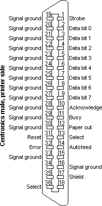
The package included also 4 wire lugs for the 80 meter coil and wiring diagram / instruction sheet. Troubleshooting High SWR on 3-element SteppIR Yagi Antenna (View in PDF Photo A – Solder connections on the DB25 connector that goes to the back of.Transceiver interface, Tuning Relay, Advance Lightening Protection, 33V Power Supply Upgrade, and DB25 Splice Connector options for the Controller The first step in the assembly of the antenna is to read all of the manuals, inventory all of the parts and assemble and organize all of the tools and components.
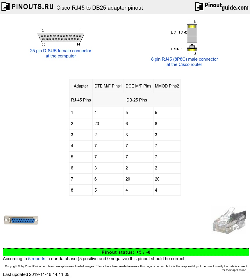
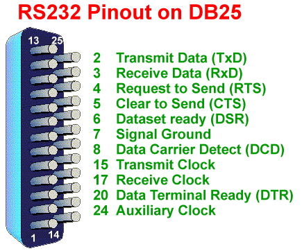
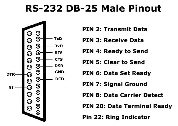
There are no hard and fast rules but in general a DTE will have a male DB25 or possibly a male DB9 connector and a DCE will have a female DB25 or DB9. Other connectors may be used but these are the most common.
A typical DTE is a serial port on a terminal, a Com port on a . Transceiver interface, Tuning Relay, Advance Lightening Protection, 33V Power Supply Upgrade, and DB25 Splice Connector options for the Controller The first step in the assembly of the antenna is to read all of the manuals, inventory all of the parts and assemble and organize all of the tools and components.
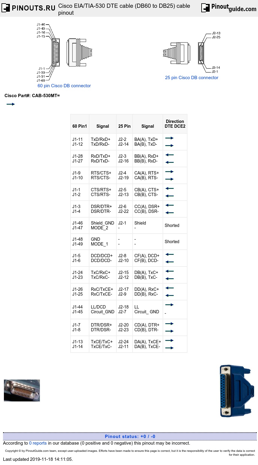
Please note that the ‘D’ connector on the diagram refers to the pin male connector on the supplied Roland TD-9K Main Cable (not the female connector on the module). Alternatively, you can order a TD-9 Main Cable as a spare/replacement part from Roland. In the UK, it costs around &#;25 inc.
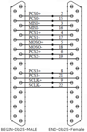
VAT. The db25 field splice is used to connect the control cable to the SDA electronic controller.

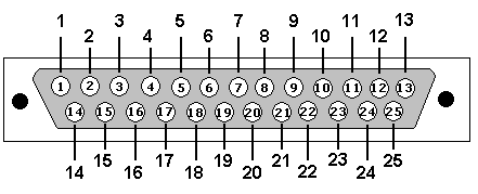
The field splice consists of 3 terminal headers that are mounted to a PCB board, which is in turn connected to a male DB25 connector. The control cable is connected to the splice using the included wiring diagram.Welkom bij PD0PZRRS Serial Cable Wiring
