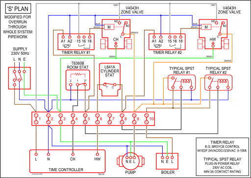
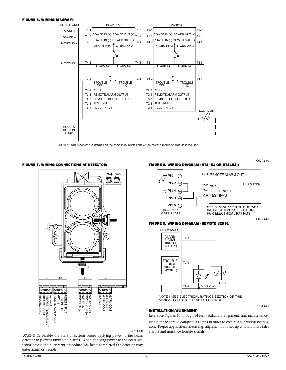
System Sensor DHACDC 4-wire duct housing will accommodate either the System Wiring Diagram for DHACDC 4-Wire Duct Smoke Detectors Using. System Sensor’s DHACDC duct detector can be used either as part of a fire detection system with a control panel or as a stand-alone duct smoke detector.
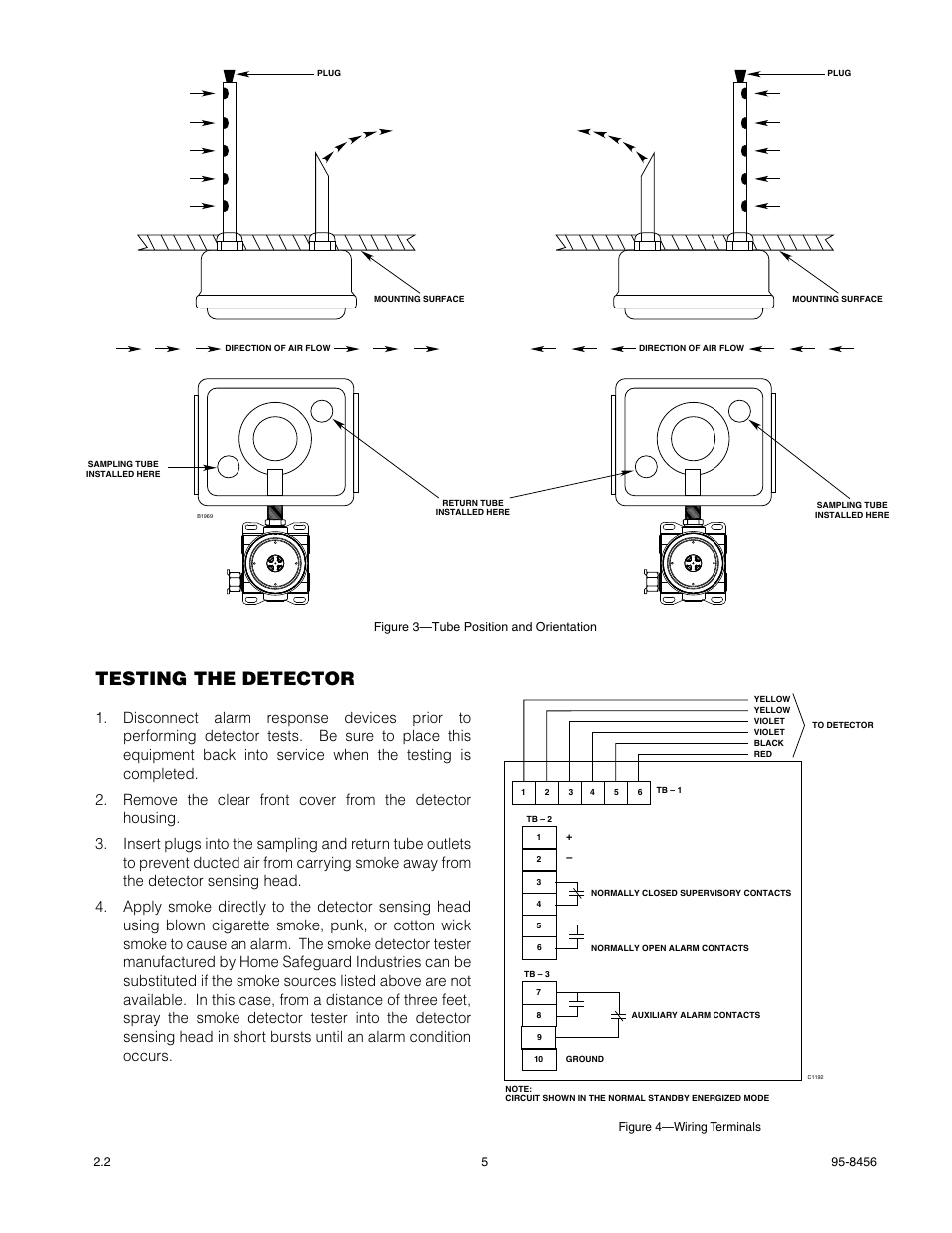
Models Available. DHACDCI Ionization Duct Smoke Detector 3-year warranty.
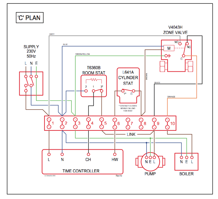
System Sensor DHACDC 4-wire duct housing will Wiring Diagram for. System Sensor’s model DH ionization detector heads or model .. Figure 6. System wiring diagram for 2-wire duct detectors (detectors powered from initiating circuit): ..
Model DHACDC Air Duct Smoke Detectors are supplied. System Sensor’s DHACDC 4-wire duct detector hous- ing will accommodate either the DH ionization sensor or the photoelectric sensor.The air duct smoke detector shall be a System Sensor Model DHACDC Series Duct Smoke Detector.
The detector housing shall be UL listed per UL A specifically for use in air handling systems. The detector shall operate at air velocities of feet per minute to feet per minute.
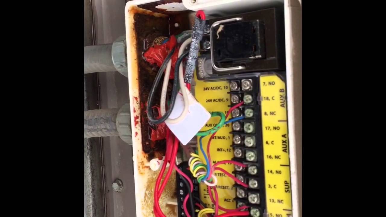
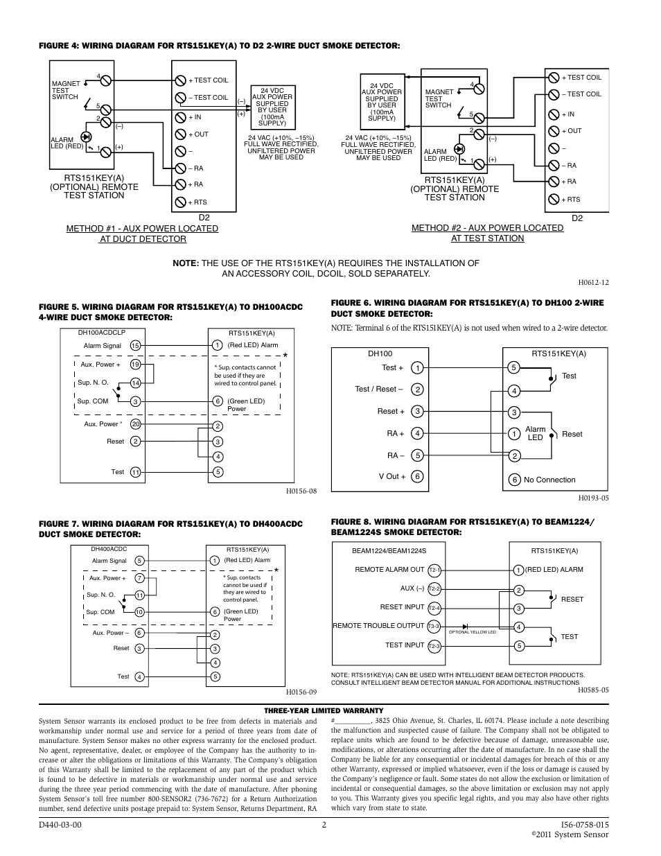
Please thoroughly read the System Sensor Guide for Proper Use of Smoke Detectors in Duct Applications (A), which Wiring diagram shown is for DHACDCLP 4-wire duct smoke detector system equipped without a control panel. NOTE: A trouble condition is indicated when the green LED is not illuminated. DHACDC Air Duct Smoke Detector INSTALLATION AND MAINTENANCE INSTRUCTIONS A Division of Pittway SENSOR2, FAX: Before Installing Please thoroughly read the System Sensor Guide for Proper Use of Smoke Detectors in Duct Applications (I), which provides detailed information on detector spacing, Wiring Diagram 6.
throughout the areas served by the duct system.
The DHACDCIHT air duct smoke detector is designed to. operate from 24 VDC, 24 VAC, VAC, or VAC.
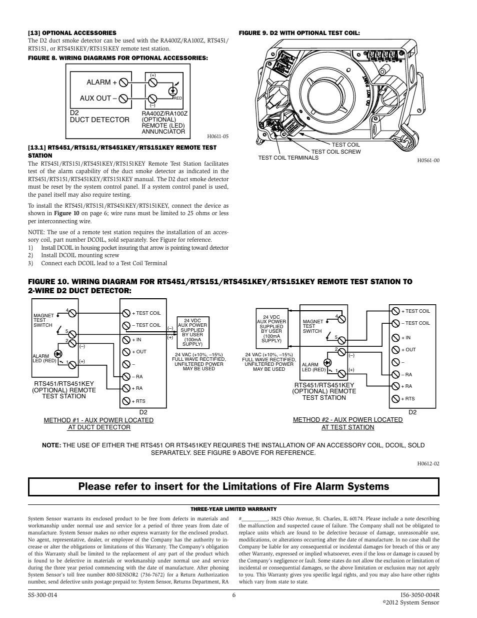
Alarm and supervisory relay contacts are available for control panel interface (alarm initiation), HVAC control, and other auxiliary functions. This detector is not designed for 2-wire. System Wiring Diagram for DHACDC 4-Wire Duct Smoke Detectors Using a UL Listed Control Panel Wiring Diagrams for Optional Accessories ALARM SIGNAL (+) AUX POWER (–) 5 6 (+) (–) DUCT DETECTOR DHACDC PA (OPTIONAL) AUDIBLE ALERT ALARM SIGNAL (+) AUX POWER (–) 5 6 (+) (–) DUCT DETECTOR DHACDC RAZ (OPTIONAL) REMOTE (LED.Product Manual: RTSSYSTEM SENSOR DHACDCLP INSTALLATION AND MAINTENANCE INSTRUCTIONS MANUAL Pdf Download.
