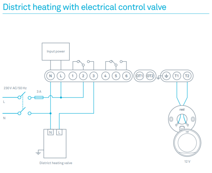
My gauges did not come with any wiring schematic. Don’t know what gages you have, but my Teleflex fuel gage, the S terminal on the gage.
Troubleshooting Teleflex Fuel Gauges. are checking should be at the position shown in the upper portion of the diagram at right.
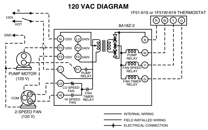
Fuel Systems (Marine) Connect two test meter wires to two sender terminals (or center terminal & flange if. This adjustable fuel gauge must be calibrated part of the tank, as shown in Diagram D. You will need to Adjustable Fuel Gauge Wiring to Tube-type Sender. Teleflex Fuel Gauge Wiring – teleflex fuel gauge wiringteleflex marine gauges wiring diagramteleflex tachometer wiring diagram.
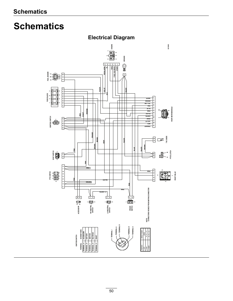
Save as PDF balance of. Automotive Fuel Gauge Wiring Diagram Most Automotive Wiring Diagram Spectacular Of Teleflex, Fuel Gauge Ideas-equus Gas Gauge Wiring Diagram.Teleflex Amega Fuel Gauge Sierra International P Lido E – 1/2 – F Dial Range Scratch Resistant Fuel Gauge, 2″ by Sierra International. $ $ 31 11 Prime.
FREE Shipping on eligible orders. More Buying Choices.
$ (20 new offers) out of 5 stars 8. Remove the gauge’s sender wire.
Turn on the power. The pointer of whatever gauge you are checking should be at the position shown in the upper portion of the diagram at right. 2.
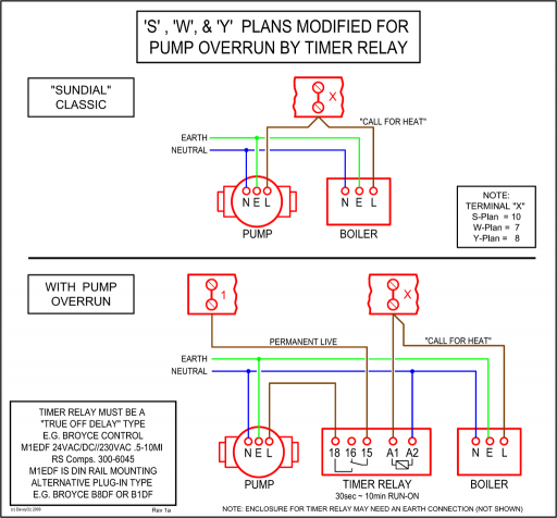
Next, take a short wire and connect to sender ter mi nal and ground terminal (shorting sender terminal to ground). Gauge pointer should be at the position.
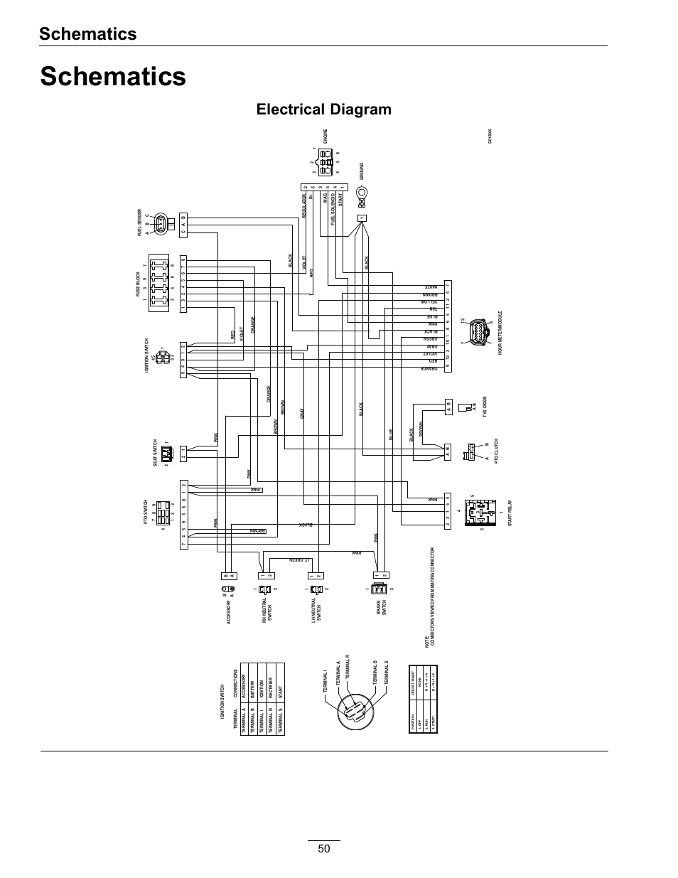
Teleflex marine gauges wiring diagram further marine tachometer wiring moreover mercury outboard tachometer wiring furthermore wiring diagram nissan micra moreover faria fuel gauge wiring diagram in addition yamaha ox66 wiring diagram further marine wire dimensions along with yamaha tach gauge wiring diagram furthermore ac dc converter circuit diagram moreover mercruiser outdrive trim wiring. Troubleshooting Teleflex Fuel Gauges.
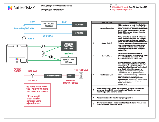
Does the Gauge Work? Gauge pointer should be at the position shown in the lower portion of the diagram.
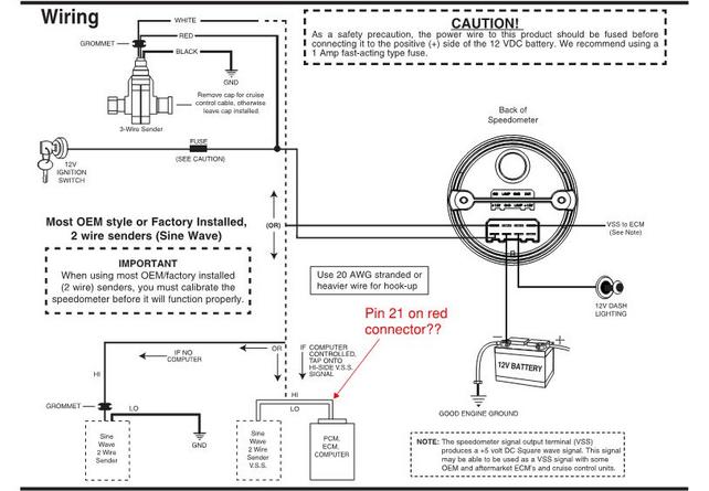
To test senders, the resistance values are shown at minimum and full gauge scales. Fuel Systems (Marine) Voltage – “I” to “G” terminal – 10 to 16 volts.
Mar 22, · This video will help you troubleshoot your fuel gauge and sending unit, to verify if it is good or needs to be replaced.Troubleshooting Teleflex Voltmeter Gaugesteleflex fuel gauge | eBay