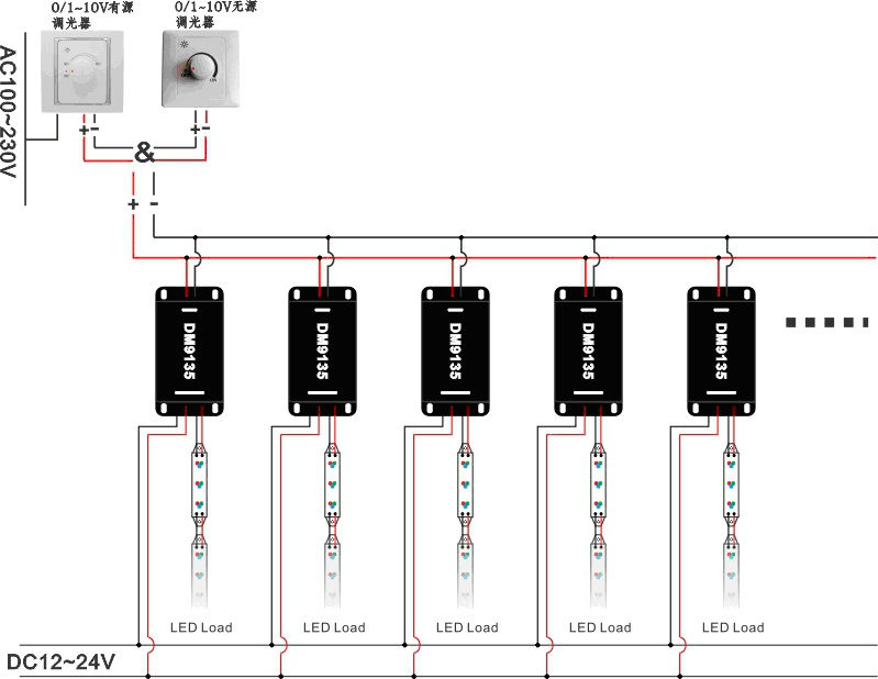
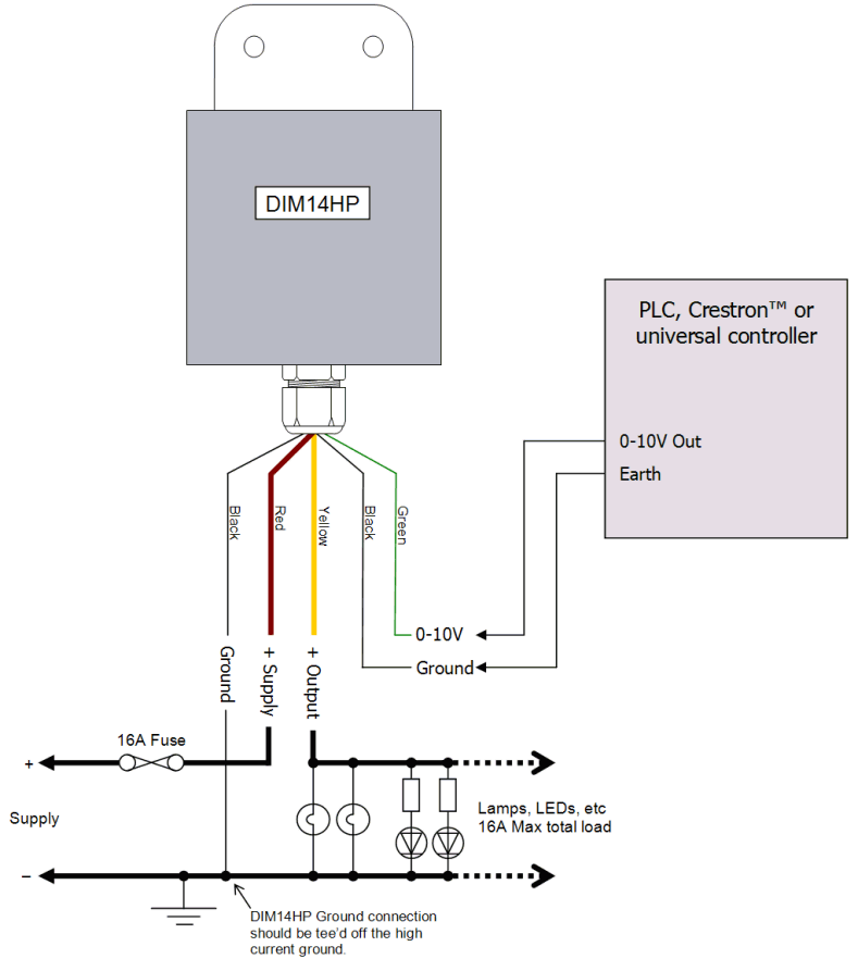
In dynamic lighting control applications, “” describes the use of an analog A dimmable LED driver includes a power supply circuit that produces. A V dimmer is considered analog dimming, and all USAI V dimming options are considered to be “sink” type dimming. A typical V wiring diagram is.
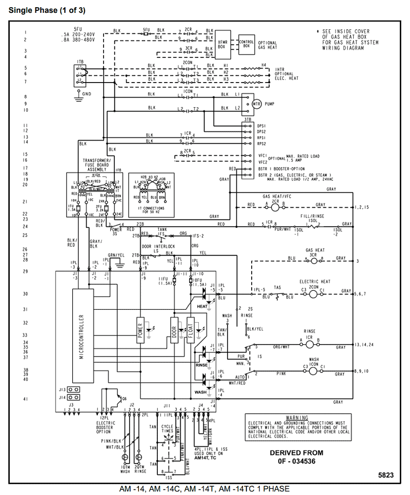
V dimming wiring diagram. V dimmer switch.
Leviton IPLFZ or equal. For other types of dimming control systems, consult controls manufacturer.
Dimming performance is ultimately limited by the quality and design of the ballast / driver. For these How many fixtures can I put on a V control circuit?. The volt low-voltage lighting control provides dimming control for volt compatible LED Wire the controls according to the appropriate wiring diagram.Feb 15, · I have no experience with volt dimming for LED and fluorescent fixtures.
I am working on a project in which I mounted GE Albeo watt LED high bay fixtures. The customer now wants to be able to dim the fixtures. These fixtures allow for volt dimming but my question is this.
What is the most cost effective way to run the control wiring? What is V Dimming?
Used as an early fluorescent dimming system and still used today, V dimming has been adapted to become a reliable LED dimming control protocol. V is one of the earliest and simplest electronic lighting control signaling systems; simply put, the control signal is a DC voltage that varies between zero and ten volts. run as Class 2.
The dimming performance of V can be impaired if the system is wired in a Class 1 configuration, especially if long distances of line voltage wiring are used. If Class 1 is desired, then actions should be taken to reduce the length of the V wires.
Wiring Details – . V dimming wiring diagram V dimmer switch Leviton IPLFZ or equal For other types of dimming control systems, consult controls manufacturer for wiring instructions switched hot (black) switched hot (red typical) low voltage dimming wires (purple & gray typical) + Electrical Panel hot (black typical) V or V, 60 Hz neutral (white. A typical V wiring diagram is shown below: V Dimming.
DIML2: Our standard V dimming driver option is often provided standard (check spec sheets) and dims down to 10% at minimum light level. It is the default dimming driver provided with our Warm Glow Dimming, Color Select and Max Output product lines, among others.Lightology | What is V Dimming?Low Voltage LED V Dimming | USAI
