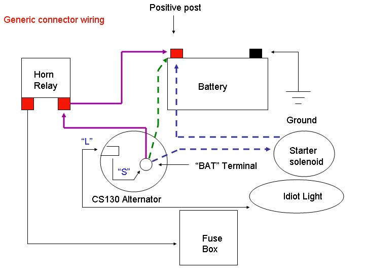
Operating principles and wiring diagram of 10Si and 15Si alternators. 10SI Alternator Wiring. The 10SI has three terminals (including those with a 1 wire regulator).
The large “BATT” terminal which gets connected to your battery. GM 10SI 2-wire Diagram 12v Neg ground · GM 10SI One wire diagram 12v Neg ground · GM 10SI One wire diagram 6v Neg ground · GM 10SI One wire diagram . 10si Wiring Diagram Tagged 10si alt wiring diagram, 10si alternator wiring diagram, 10si alternator wiring diagram with amp meter, 10si wiring.
To start off,yes I did search and couldn’t find an answer to the problem I’m having. I read all of the posts and found the proper wiring diagrams.Some other tidbits available from AC Delco for wiring up a 10SI, is wiring package (for those 6 to 12volt conversions). This contains the terminal connector AND an extra resistance wire pigtail to connect to the ignition system (don’t use a ballast resistor if you use a resistance wire).
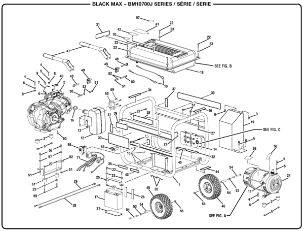
Over the years many farm tractors have been fitted with the 10SI alternator. The kits that I offer use a new 63 amp Delco 10SI cloned alternator. Each kit comes with a mounting bracket, tightener bracket, correct size pulley, diode/exciter wire, and wiring instructions and wiring diagrams.
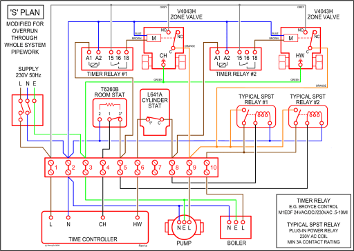
Delphi Alternator Wiring Diagram – outboard motor charging solution 2 along with packard wiring tractor wiring diagram internal regulator alternator. # vortec engine diagram.
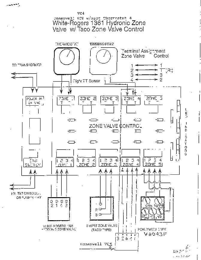
#chevy alternator wiring diagram. #10si alternator wiring. #24 volt delco 10si three wire alternator diagram.

#gm alternator wiring diagram. #delco 10si.
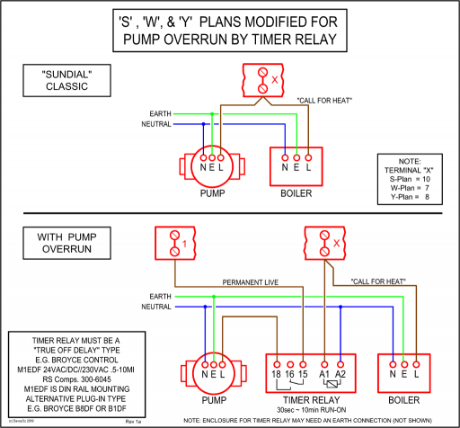
10Si Alternator Operating Principles. A typical 10Si series wiring diagram is illustrated in Figure 3.
The basic operating principles are explained as follows. The No. 2 terminal is connected to the battery, and the base-emitter of transistors TR4 and TR1 is connected to the battery through resistor R5, thus turning these transistors on. replacing delco remy 10si, 11si, 12si or bosch k1 alternators with 11si alternator REPLACING S.R.E.
BEARING IN 10SI RETROFITTING OLD STLYE DELCO REMY REGULATOR TO NEW STYLE DELCO REMY 50VR REGULATOR.10si Alternator Ground Wire Diagram | Wiring LibraryWiring a Delco (GM) Alternator