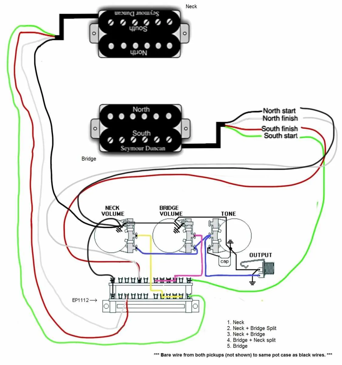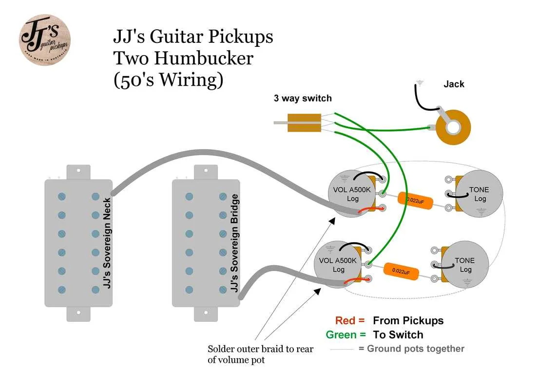
For straightforward installation of a 2-conductor humbucking pickup, connect the hot lead directly to the volume pot’s input lug and the ground lead to the back of the pot casing. This approach eliminates the need for additional splitting or coil-tapping components.
Understanding the two-core configuration helps streamline your setup. The internal coils are pre-connected, so no extra solder joints are required beyond the basic signal and ground connections. This reduces complexity and potential signal loss.
When replacing or upgrading pickups with a 2-conductor style, maintain the original grounding scheme to prevent unwanted noise. Use shielded cable where possible, and ensure all connections are secure for optimal tone clarity and reliability.
2 Wire Humbucker Connection Guide
To connect a dual-coil pickup with only two leads, follow these steps for reliable results:
- Identify the two conductors: one serves as the hot signal, the other as the ground.
- Connect the hot lead to the input lug of the volume control or pickup selector switch.
- Attach the ground lead directly to the back of the volume pot or common ground point on the guitar’s electronics cavity.
Because this type lacks separate coil taps, no coil splitting or series/parallel modifications are possible without additional components.
- Use shielded cable for better noise reduction when extending leads.
- Check polarity and phase by plugging in and listening for hum or cancellation effects.
- Ensure solid solder joints and avoid cold connections to maintain signal integrity.
This simple two-lead setup provides a straightforward connection suitable for most standard electric guitar circuits without complex modifications.
How to Identify and Prepare 2 Wire Leads for Soldering
Locate the two insulated conductors coming from the pickup assembly–typically one is hot and the other is ground. Use a multimeter to confirm continuity: check resistance between the conductors to ensure the coil is intact. The conductor with continuity to the pickup’s baseplate or metal cover usually serves as ground.
Strip approximately 1/4 inch of insulation from each conductor using a precision wire stripper to avoid damaging the copper strands. Twist the exposed strands tightly to prevent fraying, ensuring a clean and solid connection point.
Before soldering, tin both the leads and the target contact points by applying a thin, even layer of solder. This improves heat transfer and creates a reliable joint. Avoid applying excessive heat which can damage the coil’s insulation.
If the conductors are coated with enamel insulation, gently scrape or burn it off at the ends to expose bare metal. Test the exposed tips with a continuity tester to verify proper exposure before proceeding.
Step-by-Step Connection for 2-Conductor Pickup to Volume and Tone Controls

Begin by identifying the two leads from the pickup: one for the signal and one for the ground. Connect the signal conductor directly to the input lug of the volume potentiometer.
Attach the ground lead to the back casing of the volume pot, ensuring a solid grounding point. This common ground will extend to the tone potentiometer casing and the output jack sleeve.
From the volume pot’s output lug, run a connection to the input lug of the tone control. This allows the tone circuit to modulate the signal after volume adjustment.
Install the capacitor between the tone pot’s middle lug and its casing to define the cutoff frequency for the high-end roll-off.
Complete the circuit by linking the tone pot’s casing to the common ground, maintaining continuity throughout the system.
Finally, connect the output lug of the volume control to the output jack’s tip terminal, completing the path for the processed signal to reach the amplifier.
Common Troubleshooting Tips for 2 Wire Humbucker Wiring Issues
Check solder joints for cold or broken connections first. A loose or weak joint often causes intermittent signal loss or crackling noise. Resolder any suspicious points using a quality solder and a well-heated iron.
Verify continuity between the pickup leads and the output jack using a multimeter. An open circuit indicates a break or disconnection somewhere along the path.
Inspect the coil leads for damage or corrosion, especially near the connector and switch terminals. Oxidation can increase resistance, reducing output and tone clarity.
Ensure the selector switch and volume/tone pots have clean contacts and proper grounding. Dirty or faulty controls may result in signal dropouts or unwanted noise.
Confirm that the pickup is correctly phased relative to other pickups. Incorrect polarity can cause weak or hollow sounds when combined.
Test the instrument cable and amplifier input separately to rule out external issues. Faulty cables or inputs often mimic pickup-related problems.
Check for shielding continuity on the guitar’s cavity and covers. Poor shielding can introduce hum and interference into the signal.
Examine the coil resistance with an ohmmeter. Unexpected values suggest internal coil damage or partial breaks.
Replace any suspect components systematically rather than performing multiple changes at once. This approach isolates the root cause more efficiently.