Air is blown over coils at the air handler in parallel. • Each zone Use electronic VSD at the fan motor; supply and return fans should track together. Example of Schematic for Alerton Controls.
Smart Controls
Actuator Fan Powered VAV Terminal Unit. *MSH-BT ALERTON BACtalk Microset II WALL UNIT Push-buttons also support fan-speed control, and the LCD shows current fan-speed. . Immersion Sensor w/ Galvanized Junction Box ..
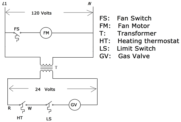
Wiring Diagrams easy parallel connection in the power system. the small footprint of the ESDk provides greater.
*MSH-BT ALERTON BACtalk Microset II WALL UNIT Push-buttons also support fan-speed control, and the LCD shows current fan-speed. .
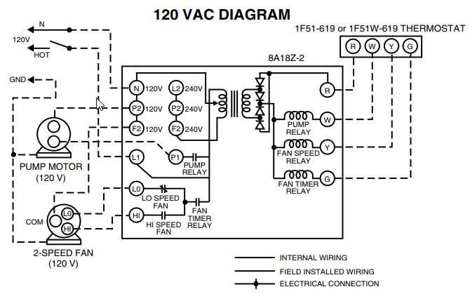
Immersion Sensor w/ Galvanized Junction Box .. Wiring Diagrams easy parallel connection in the power system. the small footprint of the ESDk provides greater.
Wiring Relays In Parallel
Alerton Dealer . System configuration diagrams in simplified block format. 2.
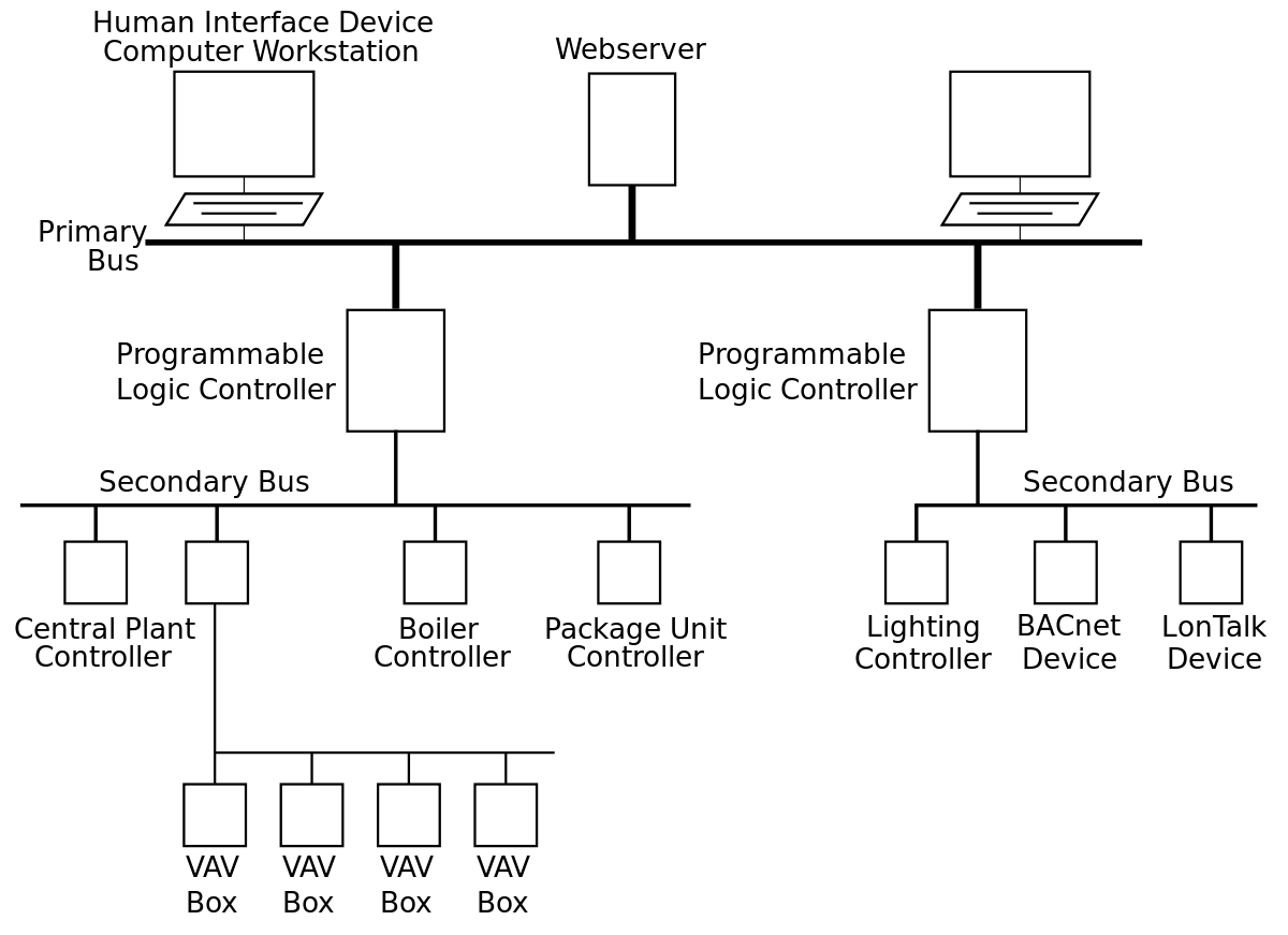
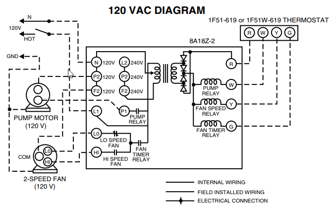
Electrical drawings that show all system internal and external connection points, For applications using variable speed parallel fans, provide a single analog. Installation and Maintenance Manual IM Group: Applied Air Systems. Part Number: IM Date: October Parallel Fan Powered.
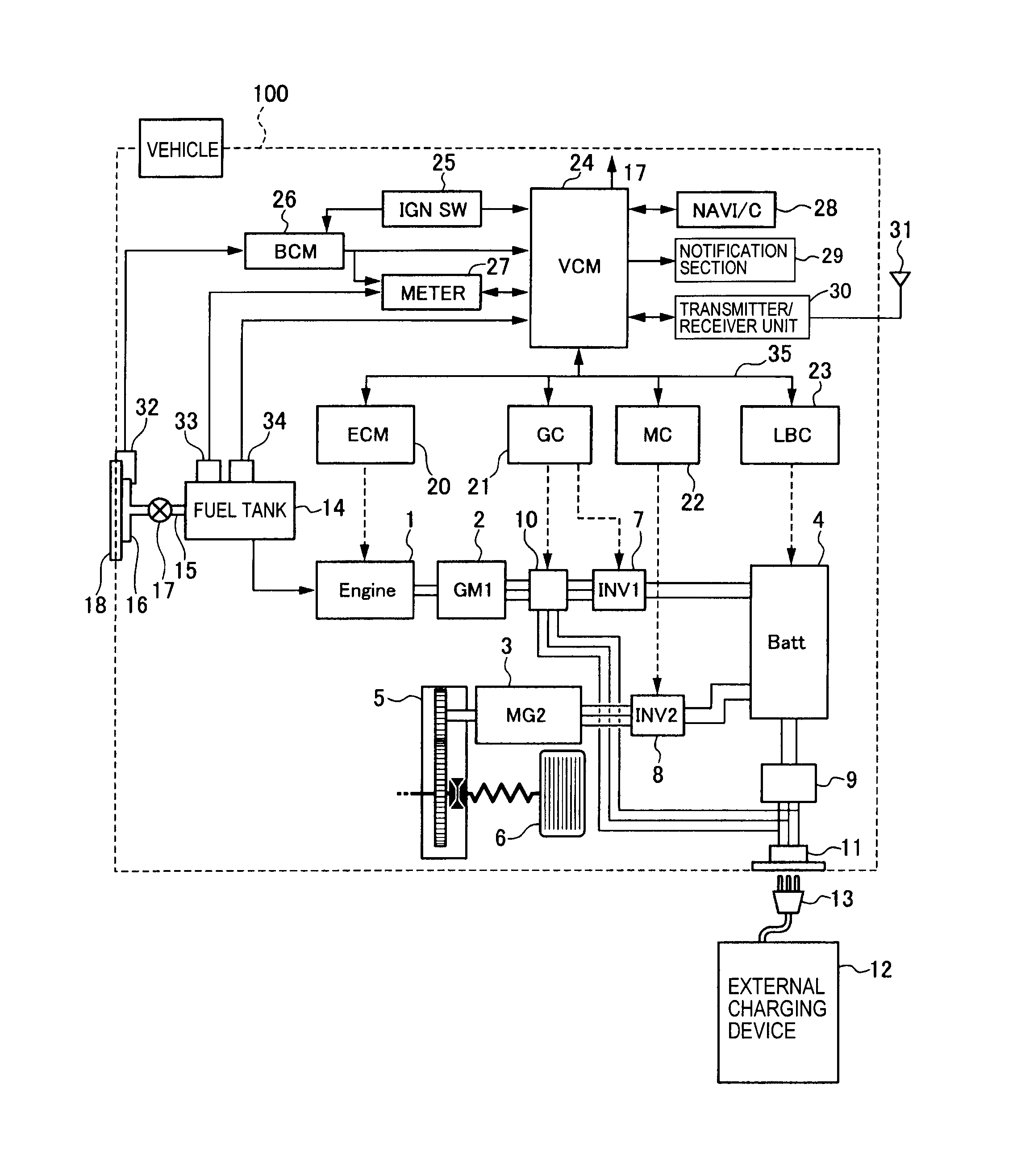
Variable Air.Wall Remote Controls and Ceiling Fan Wiring Electrical Repair Question: I have a Westinghouse ceiling fan, Wave Form. Can the remote control be taken out, and wired for a wall control? I have had three remotes for this fan, and have had nothing but trouble, any help you . I am having trouble wiring a blower motor to a fan schematron.org – Answered by a verified HVAC Technician We use cookies to give you the best possible experience on our website.
2009 Equinox Fuse Box Cover
By continuing to use this site you consent to the use of cookies on your device as described in our . system.
DDC Control Wiring Multi Stage Electric Reheat VAV System Part 1 Take 2
The AFCS wiring diagram list the proper phase, voltage, and amp load. Verify input power voltage before connecting to starters or contactors.
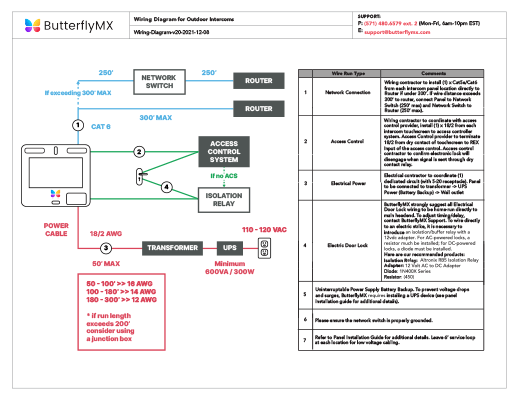
Fan Output Power: Connect output power to proper fan from contactor(s) or starter(s) terminals T1 and T2 (1 Phase) or T1, T2, and T3 (3 Phase). WIRING All wiring must comply with local codes and ord- nances. Disconnecl power beCore making wiring connec- lions to prevent elccuical shock or equipment damage.
1. Make primary connections to line voltage power SUPPlY. 2. Make secondary conneclions LO 24 Vsc control cir- cuit.
Ceiling Fan Wiring for a Wall Remote Control
3. Refer m Fig. 1 for typical wiring diagram Fig. The Alerton® BACtalk® VAV-SD2A is a versatile, BACnet-compliant field controller that provides pressure-independent control of any single-duct variable air volume (VAV) box. It is particularly suited for controlling VAV series fan boxes equipped with a variable speed fan.Underfloor Technology Case Study: Teledesic Broadband CenterCeiling Fan Wiring for a Wall Remote Control
DDC Control Wiring Multi Stage Electric Reheat VAV System Part 1 Take 2