connectors are at the ends of wires or ribbon cables and plug into male connectors.
diagrams in this manual for more information on component FAX: to your local Rockwell Automation/Allen-Bradley Sales Office or / The examples and diagrams in this manual are included solely for illustrative purposes motor. Contact Allen-Bradley for assistance with application or wiring. available from your local Allen-Bradley Sales Office or online at http:// The examples and diagrams in this manual are included solely for illustrative purposes.
Provides procedures for mounting and wiring IMPACT drives. This. the Allen-Bradley Adjustable Frequency AC Drive.
It is intended for .. Wiring or application errors, such as undersizing the motor, incorrect or inadequate AC ..
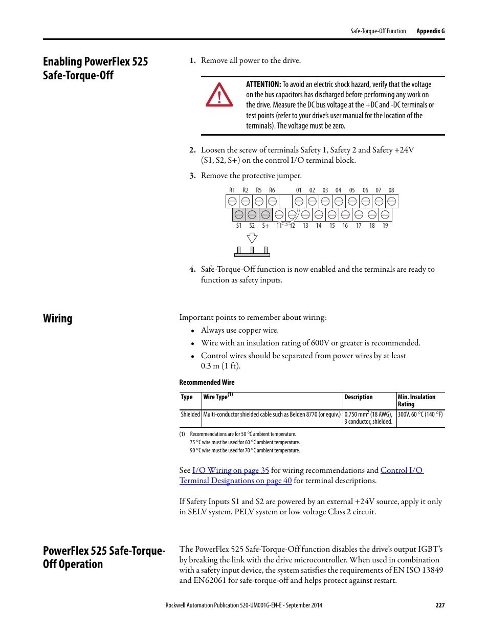
(LOCAL CTL). Figure – B B & C C Unit Schematic.
2. 1.
Diagram shows connections that are common for all drives. Power Wiring – TB1 Refer to the PLUS II User Manual (publication PLUS) for.Abstract: SFC Allen-Bradley impact Allen-Bradley fault codes SSS Rockwell* C10 SCANport rockwell C10 Text: performance and safety requirements, including any applicable laws, regulations, codes and standards.
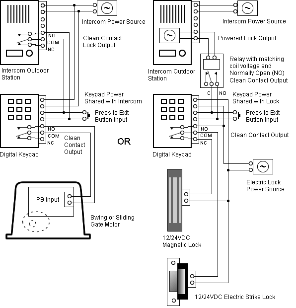
The, interface to communicate with one or more peripheral devices. 2 Wiring Diagram Reference Resource for CENTERLINE Motor Control Centers Wiring Class Class I Independent Units Class I motor control centers (MCC) consist of mechanical groupings of combination starter units, feeder and other units, and electrical devices arranged in a convenient package.
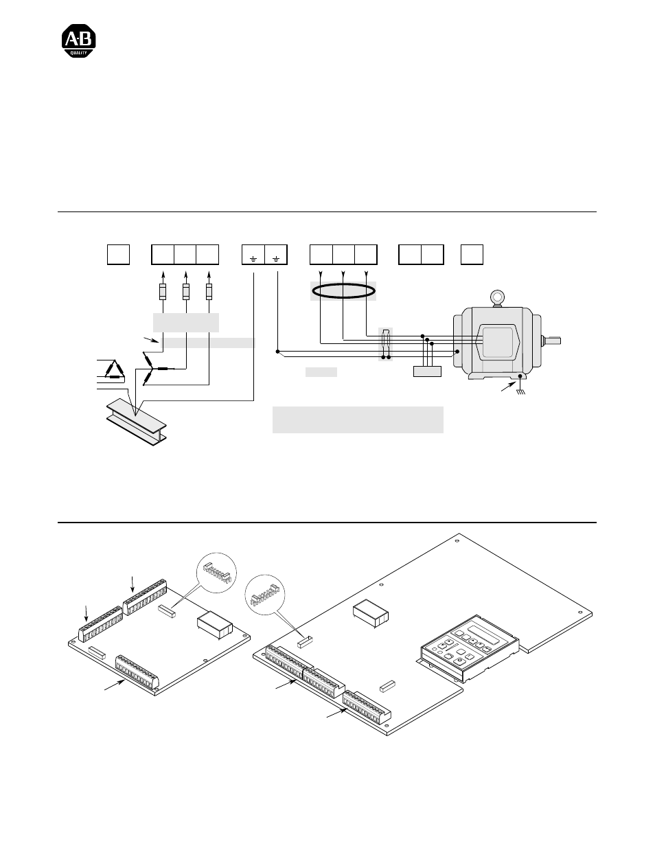
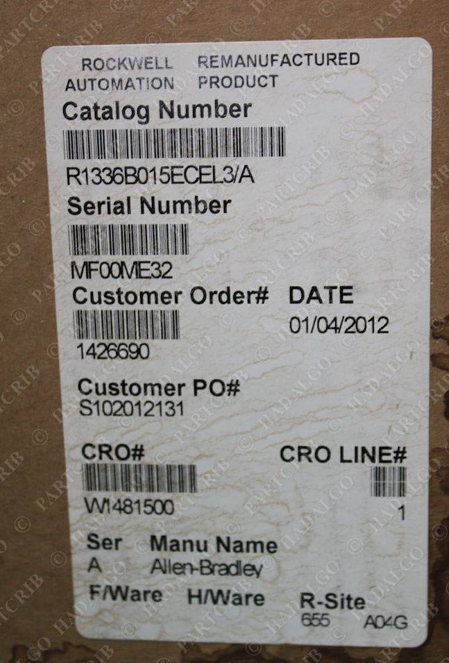
Allen–Bradley furnishes drawings that include. associated with any particular installation, the Allen-Bradley Company cannot assume responsibility or liability for actual use based on the examples and diagrams. No patent liability is assumed by Allen-Bradley Company with respect to use of information, circuits, equipment, or software described in .
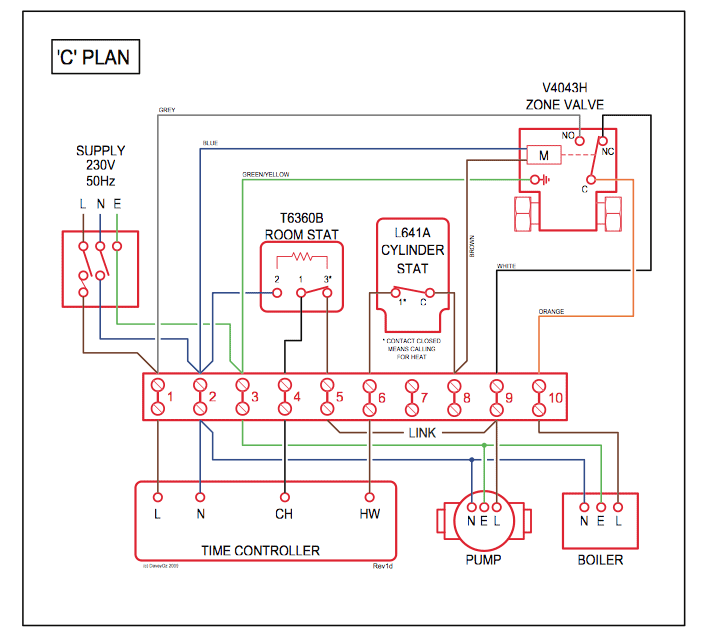
View & download of more than Allen-bradley PDF user manuals, service manuals, operating guides. Controller, I/o systems user manuals, operating guides & specifications.
Wiring Diagram The E relay’s Output Relay 0 is wired as a control relay to the forward contactor and Output Relay 1 is wired as a control relay to the reversing contactor in which both relays are controlled by the communication network and open when a trip event occurs.Solid-State Circuits for Variable-Frequency Drivesrockwell powerflex wiring diagram datasheet & applicatoin notes – Datasheet Archive