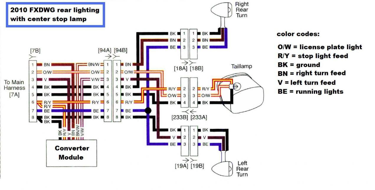
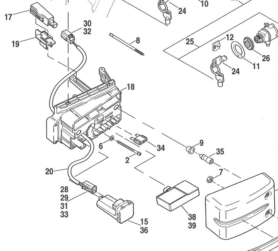
Turns your stock turn signals into running lights, brake lights and from Run to Turn/Brake modes •Comes with easy to follow diagram & connectors •Made in from 86 thru 90, with OEM 6 pin taillight connector and wires in OEM location.

# 1 ILL “The Illuminator™ module” Fits H-Ds: XL, FX and FL models from 73 thru . This module will also work well on custom motorcycles.
Badlands Turn Signal Wiring Diagram ~ here you are at our site, this is images about badlands turn. Turns your stock turn signals into running lights, brake lights and from Run to Turn/Brake modes •Comes with easy to follow diagram & connectors •Made in from 86 thru 90, with OEM 6 pin taillight connector and wires in OEM location.
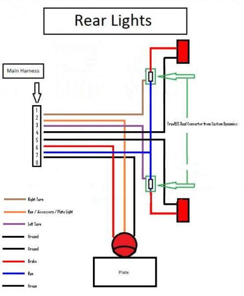
# 1 ILL “The Illuminator™ module” Fits H-Ds: XL, FX and FL models from 73 thru . BADLANDS Victory ILL-VIC Illuminator RUN-BRAKE-TURN Module with LOAD EQUALIZER are designed to provide you running light, brake light and turn signal functions to each rear turn (Sample of Victory wiring diagram of feed to.
Thank you for purchasing a Badlands Illuminator Module! we are referring to the wires that are currently running to your REAR left and right turn signals and your hooked up, (see wiring diagram below) the input wires will provide all of the.The Self Canceling Turn Signal Module™ is an electronic flashing relay that is meant to completely replace your existing mechanical flashing relay(s), or be a stand alone flashing relay to vehicles that do not have turn signals.
It works with both LEDs or incandescent 5/5(9). The Illuminator from Badlands is a plug-and-play module that solves the cut and splice issues.
Inside the Illuminator box is a sophisticated processor that turns stock taillights and turn signals into three running lights that, under braking, turn to three brake lights. Badlands turn signal module wiring also wireing diagram for starter solenoid on snapper sr mower also wiring diagrams together with bsa a10 wiring diagram further harley davidson wiring tail light signal together with nightster wiring diagram along with peterbilt turn signal wiring diagram together with harley turn signal wiring diagram equalizer together with led module wiring.
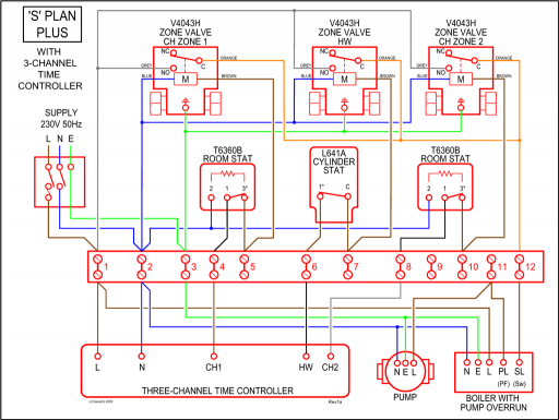
hooked up, (see wiring diagram below) the input wires will provide all of the functions the module needs to process RUN/BRAKE/TURN signal functions onto the OUTPUT wires. The objective of the diagram below is to show you to “splice into” the running light, and brake light wires using quick splices.
B A D L A N D S Illu m in a t o r R U N – B R A K E – T U R N M o d u le w it h b u ilt in L O A D E Q U A L IZ E R T h a n k y o u fo r p u r c h a s in g a B a d la n d s Illu m in a to r M o d u le!Badlands Plug In Style Run Brake Turn Signal Module ILL 01 B For Alluring Wiring Diagram – schematron.orgBadlands Illuminator Wiring Diagram – schematron.org