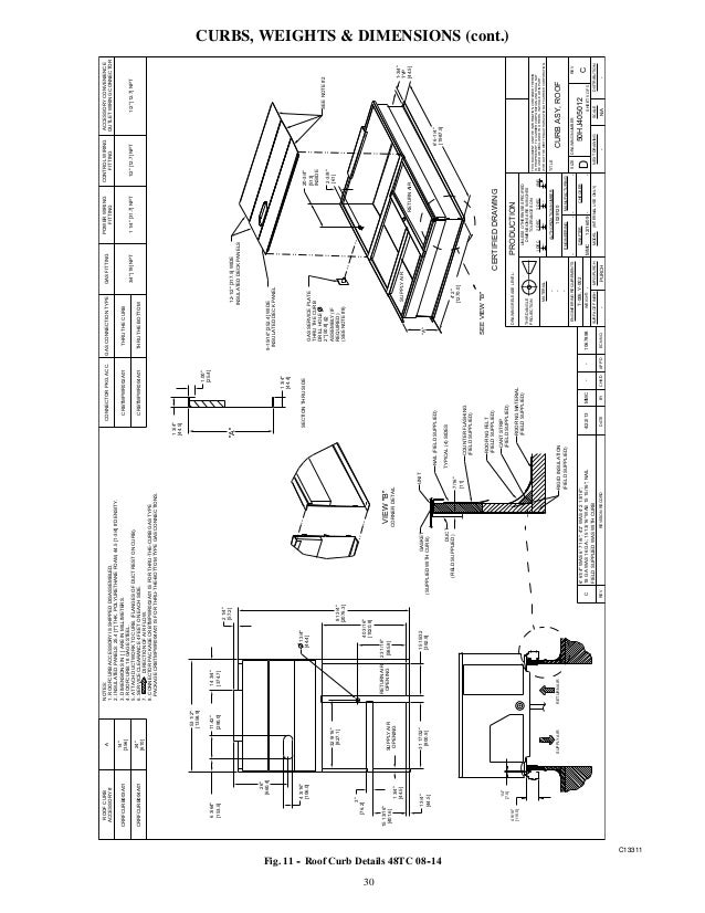
50TC rooftops fit on existing Carrier curbs dating back to tions and troubleshooting points in one convenient place .
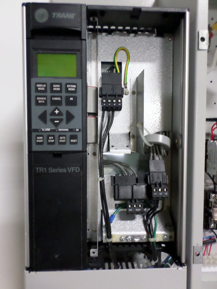
G = 2-Speed Indoor Fan (VFD) Controller. Petra PPH55 manuals · Copeland tandem compressors over amping.
mcquay rtu m. rps heat exchanger · Gordon Piatt burners · carrier 50tc – heavy.
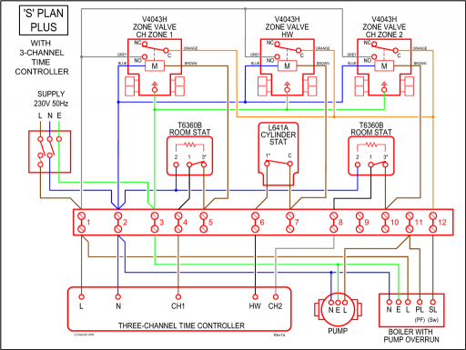
In addition, each refrigerant circuit is further protected with a high pressure and low pressure switch as well as S Standardized components and control box layout. .
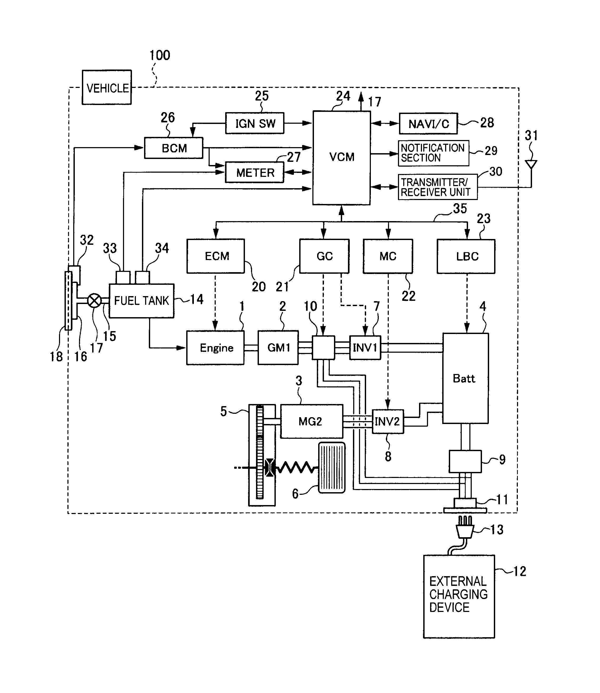
The VFD used in Carrier’s SAV system has soft start capabilities to slowly. Units are pre-wired and pre-charged with environmentally sound Puron® (R- A) refrigerant at the factory. The units are factory tested in cooling mode.
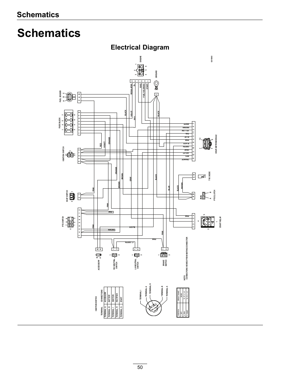
50TC. Single Package Rooftop.
Carrier 50TC Product Data: Model Number Nomenclature
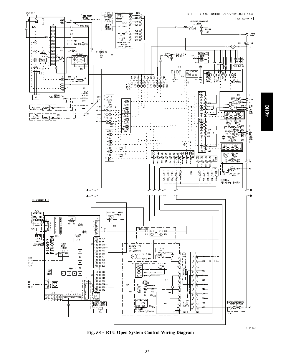
Cooling Only with Puronr (RA) Refrigerant: Sizes 08, 12, and 14 .. J = 2 Speed Indoor Fan Controller (VFD) and Non-Fused Install a Carrier–approved accessory thermostat according to installation 59 — RTU Open System Control Wiring Diagram with Humidi–MiZerR.
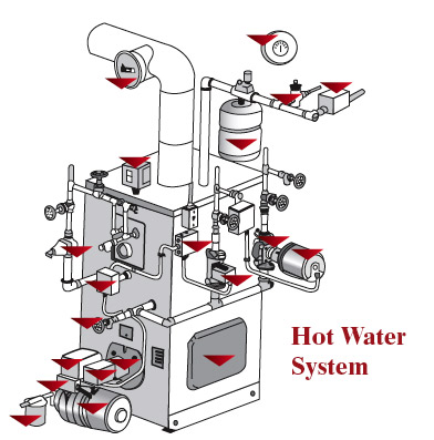
50TC.S Color–coded wiring. S Large, laminated wiring and power wiring drawings which are affixed to unit make troubleshooting easy.
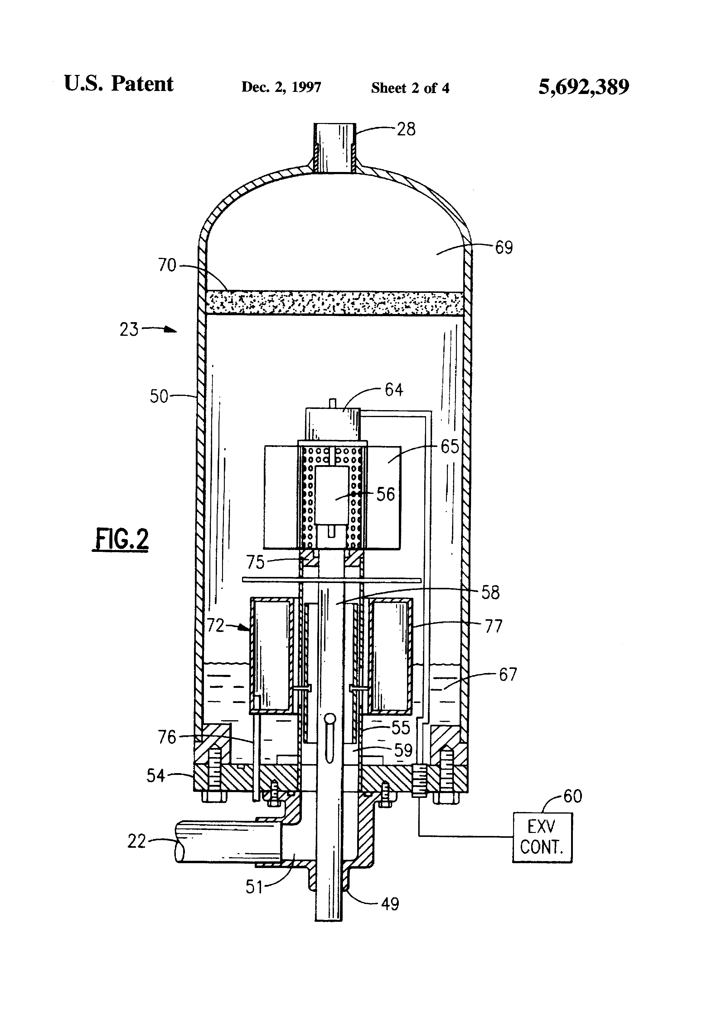
S Single, central terminal board for test and wiring connections. S Fast–access, handled, panels for easy access to the blower and blower motor, control box, and compressors.
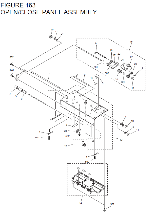
50TC WEATHERMAKER® rooftop unit were designed by customers for customers. With a gauge plug, centralized control center, plug & play accessory board, “no-strip screw” collars, and handled access panels, we’ve made the unit easy to install, easy to maintain, and easy to use.
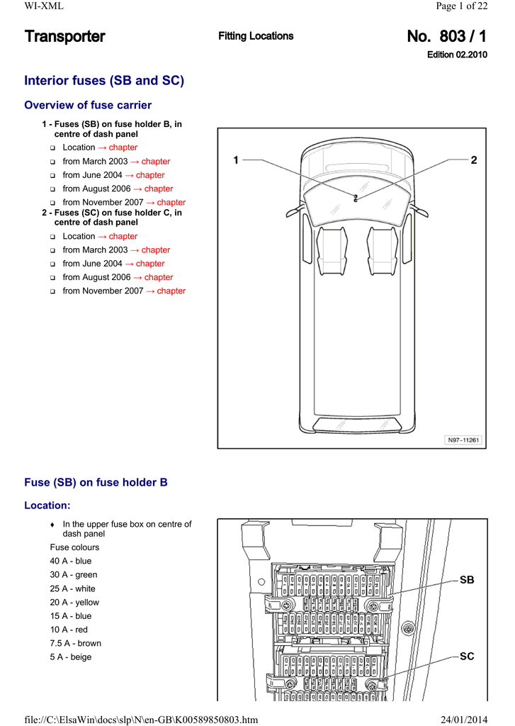
CCN — Carrier Comfort Network VFD — Variable NOTES: 1. Factory wiring is in accordance with the national electrical codes. Any field modifications or additions must be in compliance with all applicable codes.
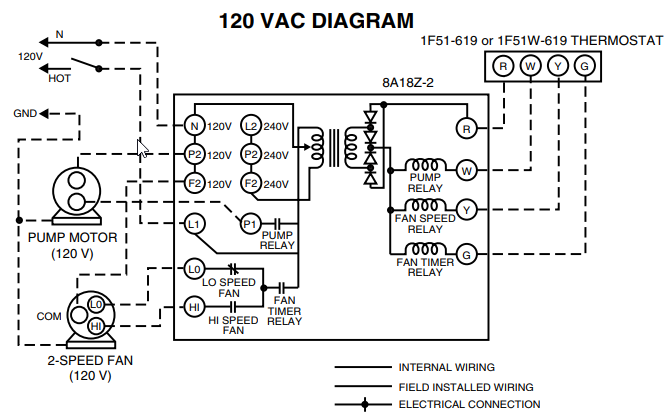
2. Use 75° C min wire for field power supply, use copper wires for all units.
Large, laminated wiring and power wiring drawings which are affixed to unit make troubleshooting easy. Single, central terminal board for test and wiring connections.
Fast-access, handled, panels for easy access to the blower and blower motor, control box, and compressors. Northwell Health®’s Huntington Hospital will save 10% on energy costs annually, about $,, and earn more than $, in additional energy rebates from Public Service Energy Group due to the installation of a Carrier® 30XV air-cooled chiller system.Installation, Setup & Troubleshooting Supplement – PDFCARRIER 24ACB7 COMFORT WIRING DIAGRAM Pdf Download.
