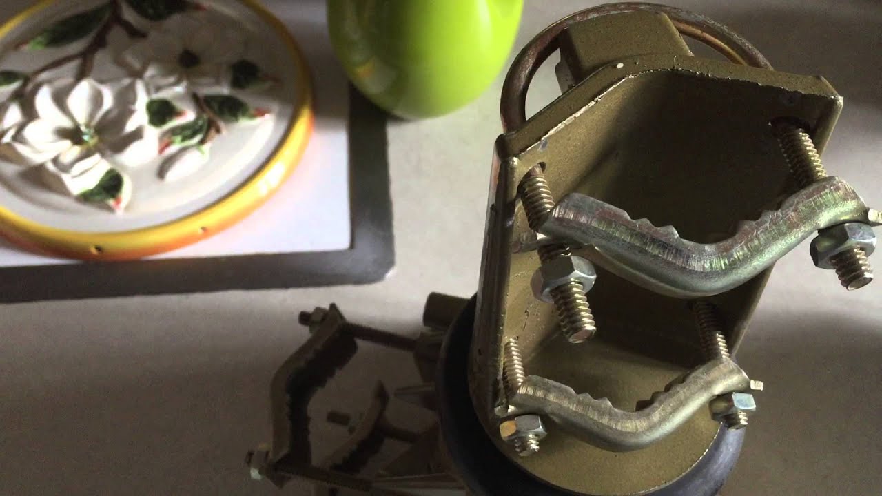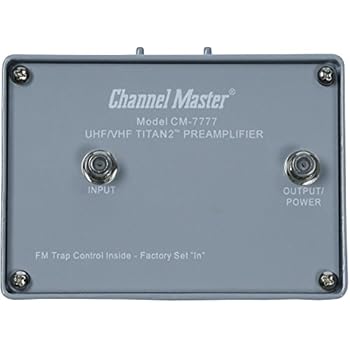
Channel Master® – Models , (A), , , (A) Antenna. Do not mount citizens band base station antennas on top of a standard mast mount drive unit.
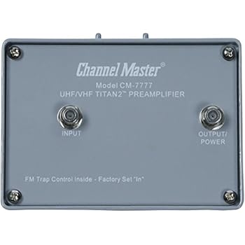
.. Check the wiring between the controller and the drive unit.
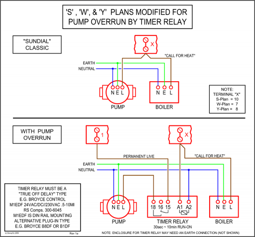
Appendix. channel master wiring diagram – Televison & Video question.
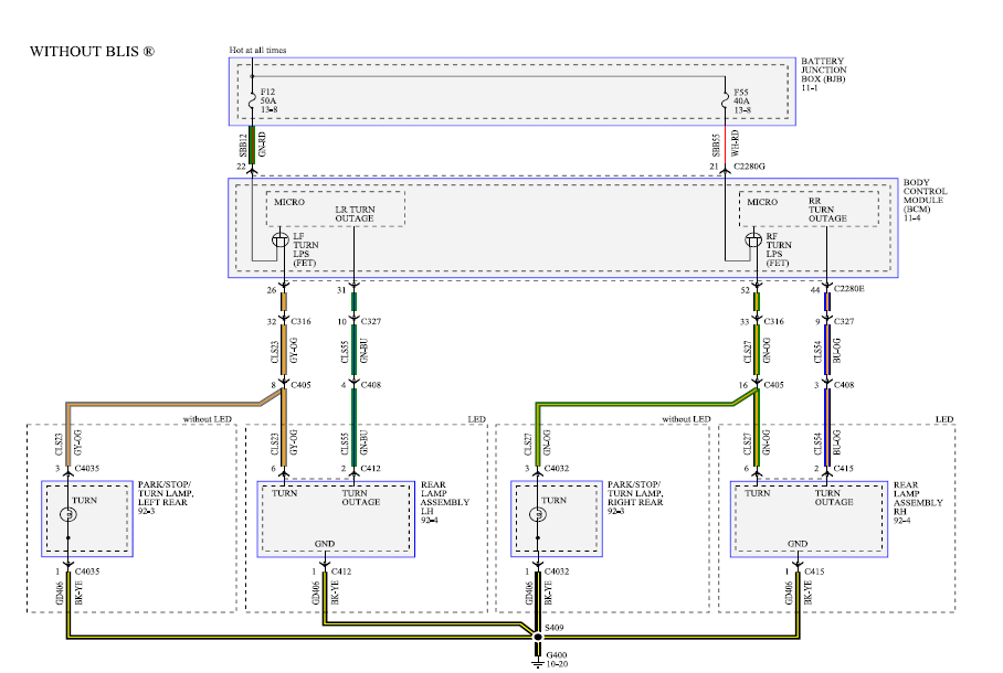
NOTES: Channel Master cannot guarantee universal handheld remote control compatibility. Check the wiring between the controller and the drive unit. APPENDIX D .
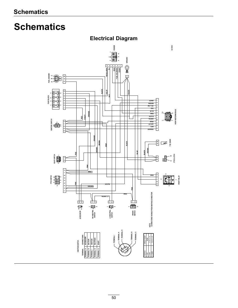
Channel Master Models: CM, (A), , , ( A). If you have a Channel Master model drive unit it can be installed to rotate your existing television antenna.

The Channel Master is a rotor that turns an antenna to adjust the television signal for the best reception. You can connect a Channel Master model by first. Channel Master® – Models , (A), , , (A) Antenna.
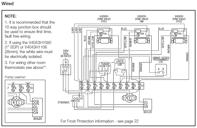
Do not mount citizens band base station antennas on top of a standard mast mount drive unit. .. Check the wiring between the controller and the drive unit.
Appendix.Jul 26, · Possibly broken control unit for antenna rotor. Possibly broken control unit for antenna rotor.
Skip navigation Rotor Control Unit Channel Master A HighTechify. Loading.
Channel master model A need wiring help the control has 3 posts marked 1 2 3 I have red black and white wires – Televison & Video question Search Fixya Press enter to search. The Channel Master is a rotor that turns an antenna to adjust the television signal for the best reception.
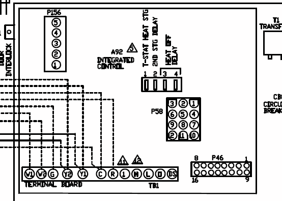
Connecting the rotor is the process of wiring the base unit and the control unit to adjust the antenna from inside the house. You can connect a Channel Master model .
Channel Master ® – Models CLASS 2 WIRING MAY BE USED. WIDE WIRE 18VAC 1 AMP Terminals Connections Green Wire #1 to #1 Black Wire #2 to #2 Red Wire #3 to #3 The exclamation point indicates the presence of important operating and maintenance (servicing) instructions in the literature accompanying the appli-. Antenna rotor wiring diagram fresh tv aerial diagrams of tv antenna installation linestor wiring diagram channel master at rotor 6 tv antenna installation linestor wiring diagram channel master at rotor 6 archerotor 15 b wiring diagram channel master automatic antenna rotator control model a you at channel master rotor wiring.How to Connect a Channel Master Model Antenna | It Still WorksHow to Connect a Channel Master Model Antenna | It Still Works
