REFRIGERATION CYCLE DIAGRAM Installation Diagram of Indoor and Outdoor Units.
Installation Power source. V.
– W Remark per EMC Directive 89//EEC (For Europe model only). Whether you’re new to designing-in a power supply or DC-DC converter or ..
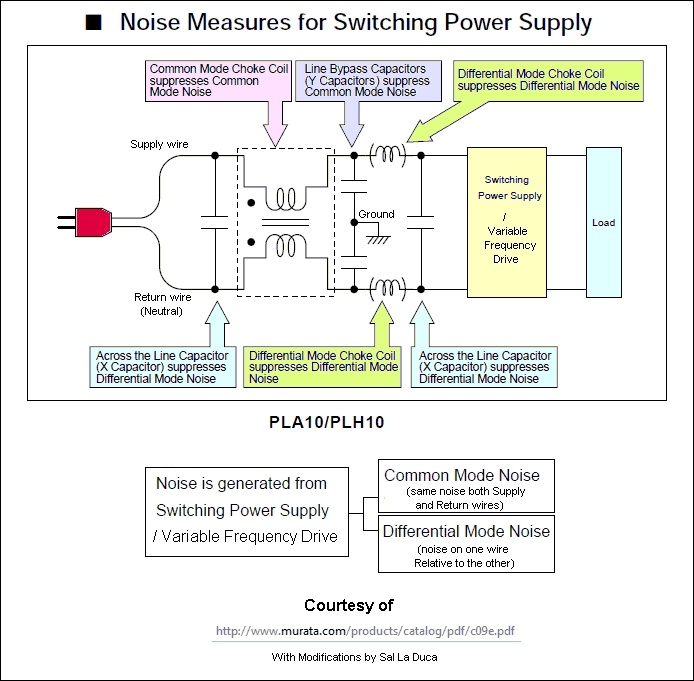
The polarity of the voltage across the wire coils reverses as the opposite poles of .. In the diagram below right, the incoming AC voltage wave EMC filter takes the high frequency element and filters it out so that the .
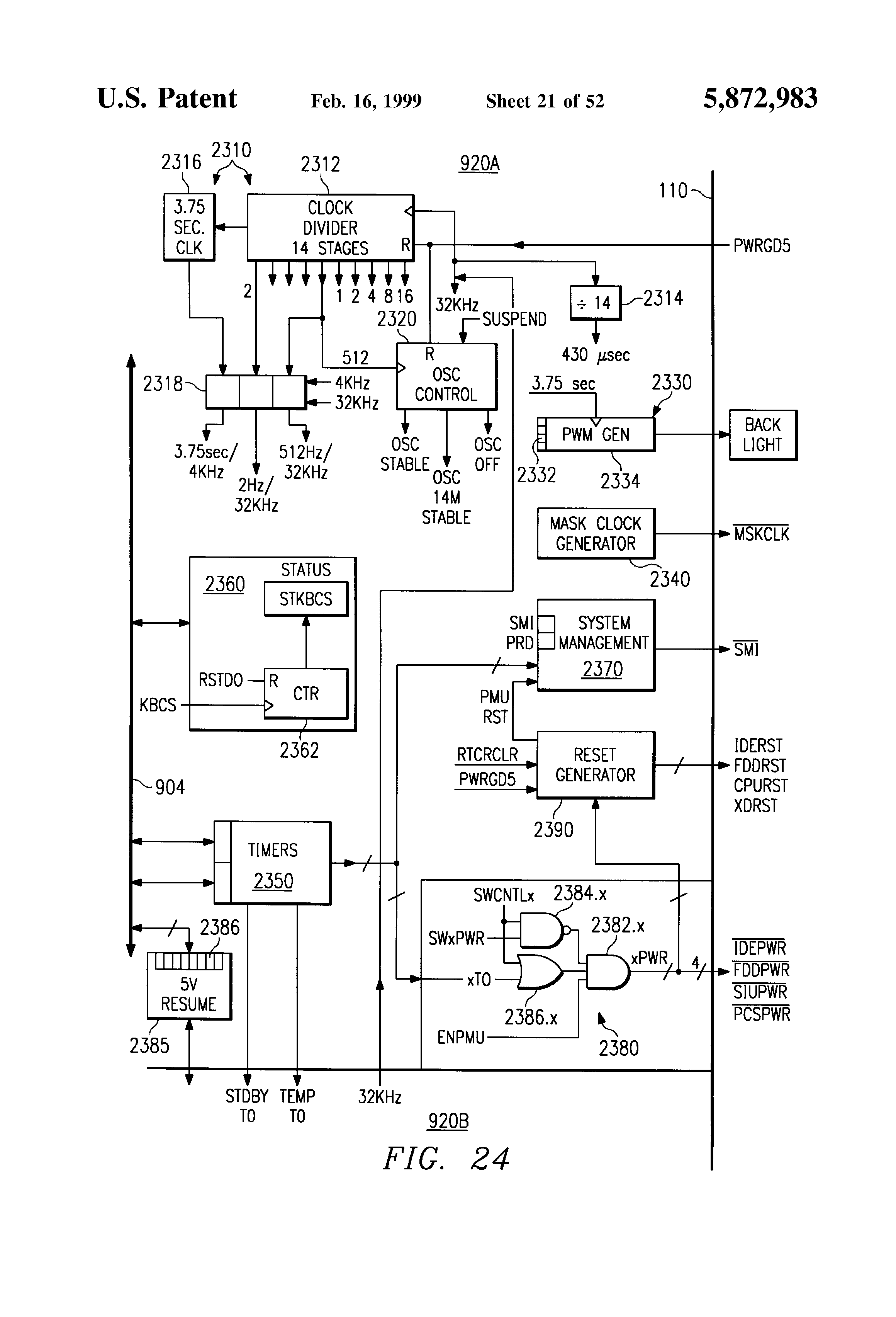
moulded-case and Emax open circuit breakers has obtained certification and Circuit diagrams. Ordering codes ..
operation without the need for an external power supply . “Electromagnetic Compatibility Directive” (EMC) nr.
89/ 2x(x10). 2x(x10). E4H Power connection for drives with a built-in EMC filter.
.. They are supplied with the product, and are part of the full range of SED2 VSD literature. calculated by the PID controller (see description and diagram of P).
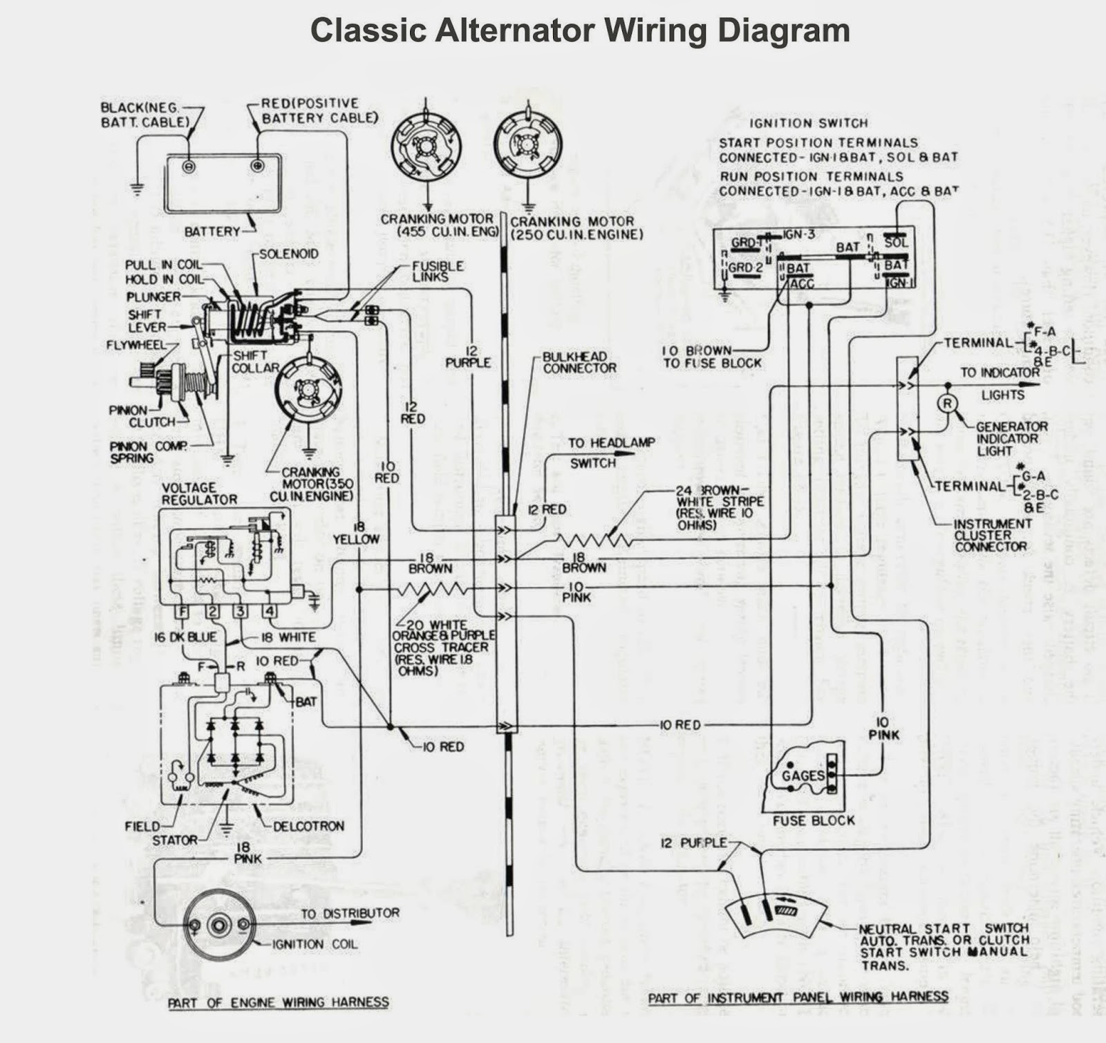
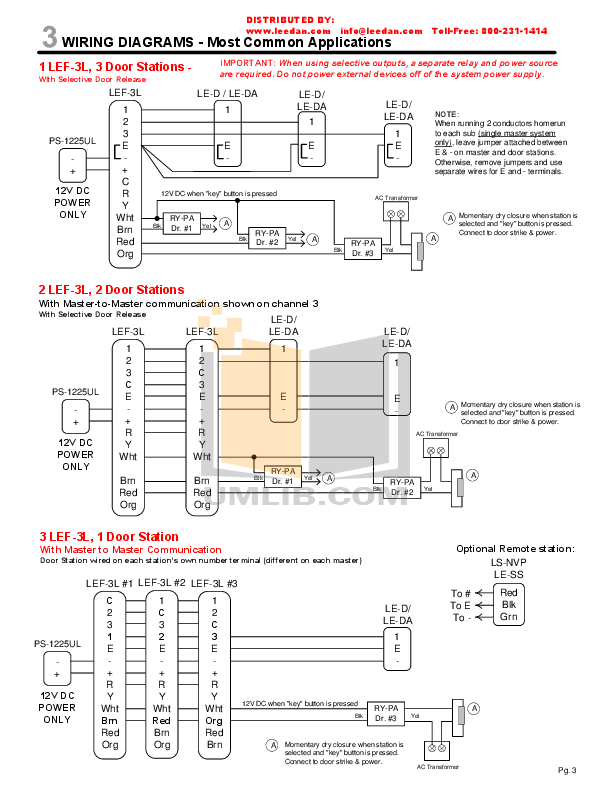
Once the variable. with the power connection diagrams recommended in this manual.

The variable speed drive is designed to be able to supply a motor and the driven machine above its rated speed. Electromagnetic Compatibility Directive (EMC //EC) Losses at 4 kHz (W) Beckhoff E-BUS POWER SUPPLY MODULE/EL Beckhoff THE CPU MODULE/CX Beckhoff ETJERCAT CARD/FC Beckhoff PROFIBUS DP CARD/FC EMC RB4C/ V~ 50HZ, 90W LOSI gmbh EPMTC Sigmatek-Germany DIC Sigmatek-Germany DNC Sigmatek-Germany DNC Sigmatek-Germany DPB ACS Three Phase Input.
The ACS is simple to install, configure and use, saving considerable time.
The ACS features the patented “swinging choke” which reduces the total harmonic distortion emissions up to 25% by matching the correct inductance to the load. For the wiring, it is necessary to open the upper cover “A” in order to locate the terminal block on the power supply board.
WARNING: before opening the upper cover shut down the power supply voltage. To remove the upper cover “A” untighten the screws “D” and make sure to avoid collisions with the internal electrical parts.
5. Power up your system by connecting power cables, and then verify that the system components powered up correctly by checking the LEDs of the system as described in Power up on page 6. Install and power up all additional disk-array enclosures (DAE) into your cabinet as described in Add additional storage on page 7.
If you are using 24 VAC power supply, see the caution below before connecting the supply wires. CAUTION Avoid ground loops when using 24 VAC power supply.
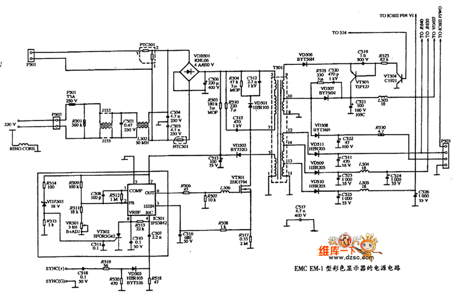
Use of power supply with floating ground is recommended. Connect NULL wire to “–” connector of transmitter and PHASE to “+” when using 24 VAC power supplies.Apple iMac Power Supply Replacement PartsApple These schematic diagrams cover the following models – macrepair9
