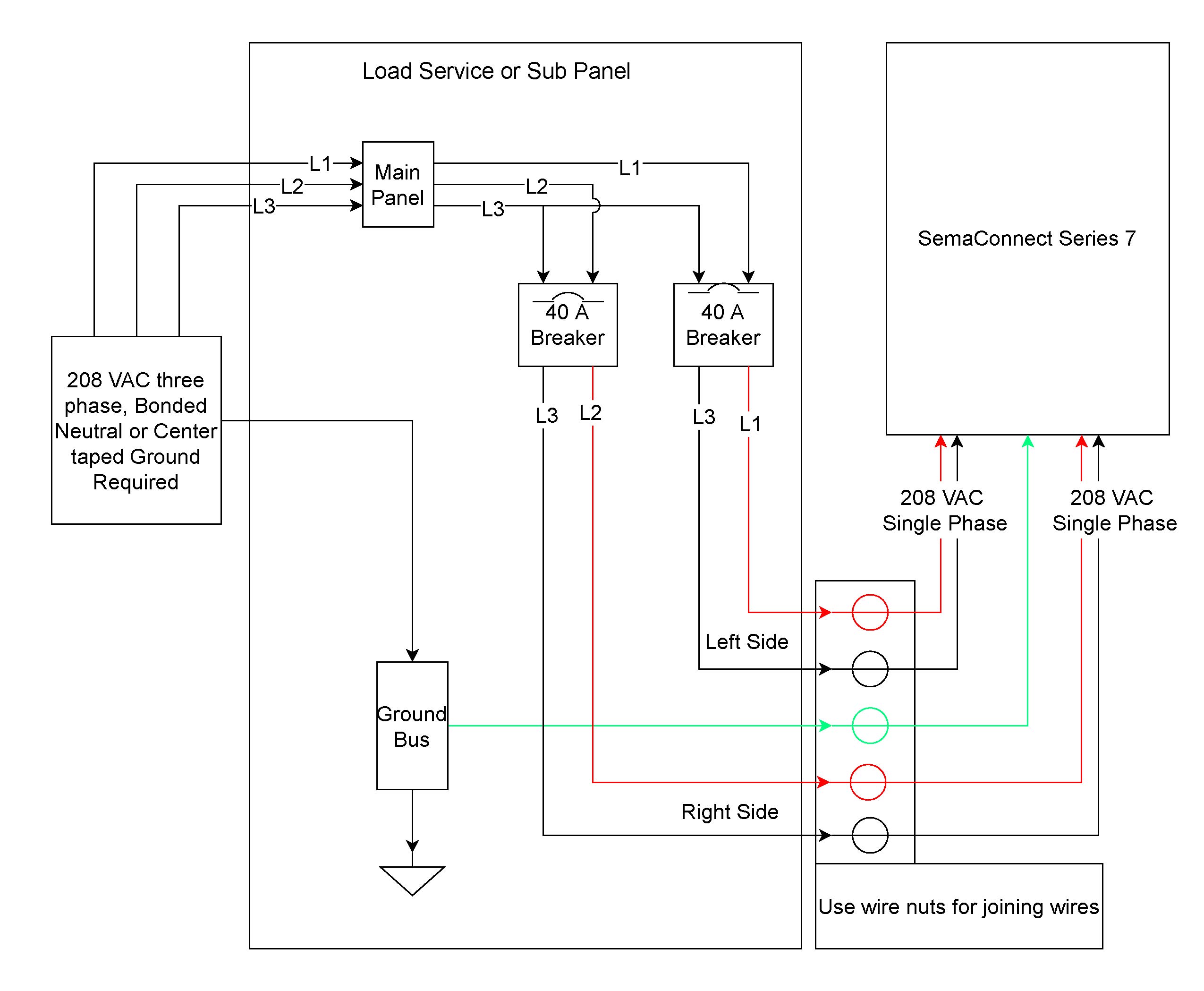
The ONW-PRR7 allows the control of four GE RR7/9 relays or two Sierra Wire units as shown in wiring diagrams per applicable voltage requirements. Problem with GE RR7 low voltage relay.
Discussion in I have the bad feeling that we have blown the RR7 relay. From what I have found . There are many links to diagrams online that I will include in this schematron.org must.

My home has this old GE control system for all switches. There are 56 At $$ 40 per RR7 relay, I cant afford to blow them out at a higher rate than they are normally supposed to last.
.. The wiring diagram is as follows.
New GE RR7 maintained relay switch comes equipped with 3 low voltage leads and is the best replacement option for discontinued GE relays for standard unlighted switches. I have an old GE RR2 remote control relay switch in my home.
The GE RR7 low voltage relay is a direct. GE low voltage wiring switches, relays and junction box (C) InspectAPedia .
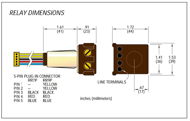
See Three-wire to Touch-Plate® Wiring Diagram. 28VDC latching relay, whereas the the GE® relay (RR-7) is a dual coil, 24VAC latching relay, and the Remcon®.The relay should “click” and the Relay Indicator should change state.
Confirm the operation by measuring the continuity at the line-voltage terminations of each relay. 2.
Apply power to the relays. Being careful not to touch any line-voltage wiring, toggle each relay ON/OFF again and confirm that each relay controls the appropriate load. Jun 25, · Here’s how it works: The GE RR7 relay is a ‘latching relay’. This simply means that when you touch a light switch to turn on a light, it sends a pulse of low voltage (24 volts DC) to the relay on the RED wire and latches it ON for the light to be switched on by the relay. It requires a pulse of voltage on the BLACK wire to turn it OFF.5/5.
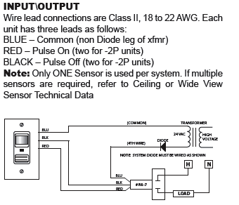
V star wiring diagram also ge rr7 relay wiring diagram furthermore victory motorcycle wiring diagram furthermore location of vin on victory motorcycle moreover yamaha v star wiring diagram along with yamaha v star wiring diagram further ge rr7 relay wiring diagram along with wiring diagram for a fleetwood terry also. Read this Kyle Switch Plates exclusive instructions for installing newer GE RS2 series low voltage switches in remote control wiring systems using RR7, RR8 or RR9 mechanical relays 5/5. GE RR7 – 20A SPST Low Voltage Relay Total Lighting Control.
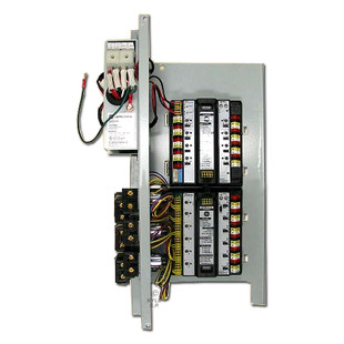
GE Model RR-7 isa mechanical latching-type unit requiring only momentary 24 VAC switch circuit pulses to open or close line voltage circuits. All GE low voltage relays may be used to full-rated capacity for tungsten filament, 2/5(1).How to replace a ge rr7 with a remcon r – FixyaDiagram: Ge Rr7 Relay Wiring Diagram
