
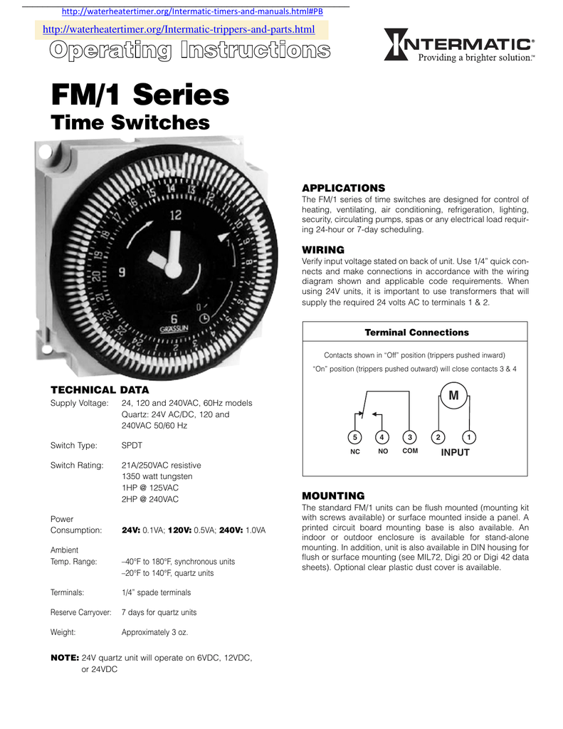
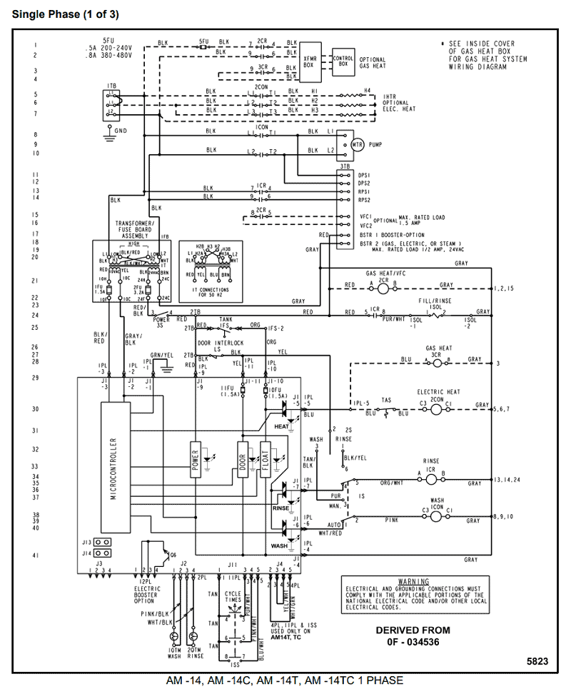
Here’s the wiring diagram: schematron.org~/media/files/intermatic/ products/instructions/timers/t%%schematron.org The wiring. Disconnect power at the circuit breaker(s) or disconnect switch(es) before installing or servicing. • Installation doivent être utilisées.
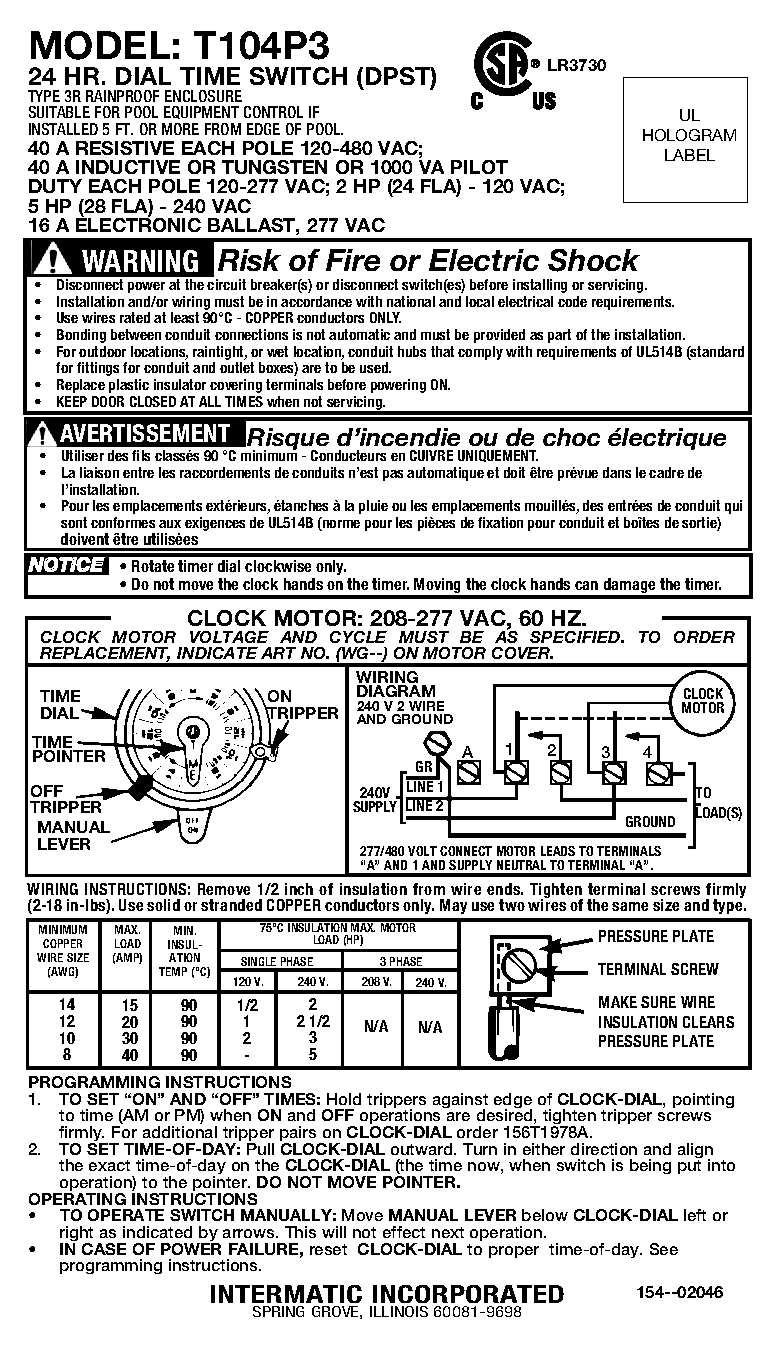
LR CLOCK. MOTOR.
WIRING DIAGRAM. FROM.
V INTERMATIC INCORPORATED. SPRING. Intermatic -Simple, Affordable Controls.

News & Events · Policies · Intermatic Store. Home» Wiring» Wiring Diagrams.
Email Print Bookmark. Wiring Diagrams .
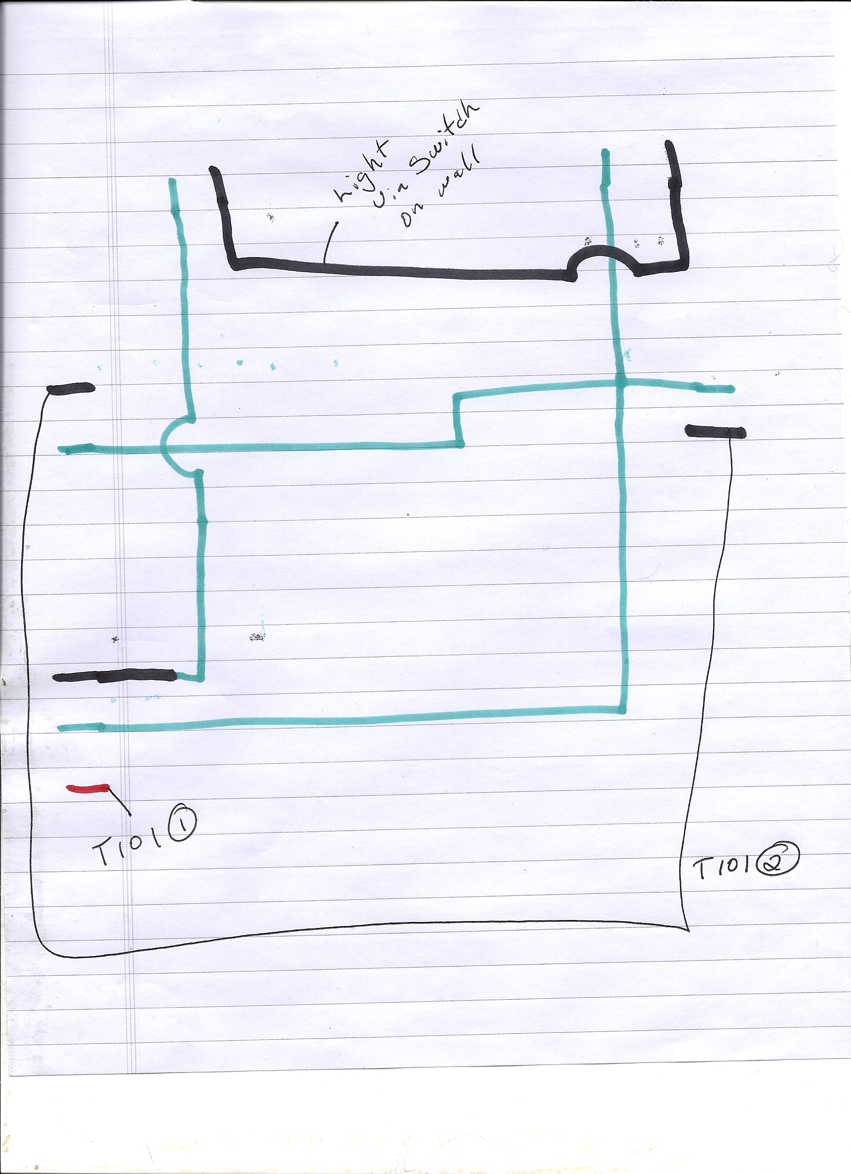
For replacement parts contact Intermatic Customer Service or visit: LABEL. LR CLOCK MOTOR: VAC, 60 HZ. INTERMATIC For terminal markings, internal wiring and contact arrangements refer to wiring diagram above .
Sign-up for email alerts for products and software updates, new product releases and information about upcoming events. Sign Up. Intermatic.
Global. |. English.intermatic incorporated ts spring grove, illinois time pointer time dial off tripper manual lever on tripper clock motor ground a 1 2 grd.

v supply to line load neut. wiring diagram pressure plate terminal screw make sure wire insulation clears pressure plate minimum copper wire size (awg) max.
load (amp) min. insul-ation. Within both home and work environments Intermatic has Within both home and work environments Intermatic has been a leader in innovation for timing switches and energy controls for more than years.
The T Series Electromechanical Time Switches are designed for industrial commercial and residential applications. How To Install an Intermatic T Timer How To Install an Intermatic T Timer WRITTEN BY: Inyo Pools In the wiring diagram is says neutral..
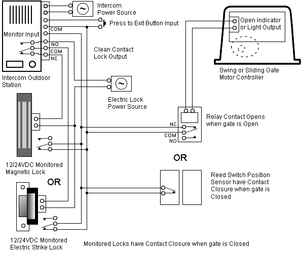
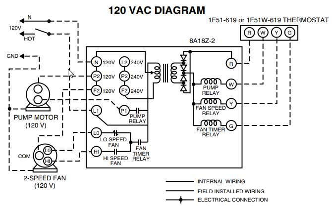
when I connect it to the white neutral bar in the fuse box it trips the gfi same if I connect it to the ground bar this is a double pole switch with GFI. intermatic incorporated ts spring grove, illinois time pointer time dial off tripper manual lever on tripper clock motor ground a 1 2 grd.
v supply to line load neut. wiring diagram pressure plate terminal screw make sure wire insulation clears pressure plate minimum copper wire size lr document1 10/30/03 pm.
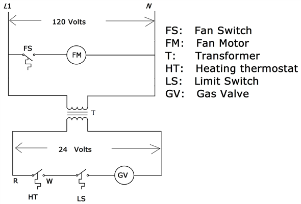
WIRING DIAGRAM V 2 WIRE AND GROUND LR UL HOLOGRAM LABEL WARNING Risk of Fire or Electric Shock • Disconnect power at the circuit breaker(s) or disconnect switch(es) before installing or servicing. • Installation and/or wiring must be in accordance with national and local electrical code requirements.SOLVED: Need wiring diagram for the Intermatic SS5C70 or – FixyaSOLVED: Need wiring diagram for the Intermatic SS5C70 or – Fixya
