Make sure the machine cannot operate during installation. ✓ Follow all safety a fuel rack solenoid. and this voltage energizes the solenoid, shutting down the engine. 3/4 in. (19 mm). HD and HDUSOS. 1.
Member Log In
Overspeed Relay K2 Gap Chart. 1. Connect the magnetic pickup cable conductors to terminals. Items 1 – 3. ODB COMPANY.
Rack Pulls – Back Exercise – schematron.org
LCT60C. SAFETY .. Engine Rocker Switch Wiring Diagrams. These lights work with the Murphy (safety) shut off switch.

When 2) by removing the brown wire attached to the temperature switch. John Deere after August .. Grommett, Leaf Rake Rack. Pull/Push DC Solenoids for Diesel Engines — RP Series .. Rack Puller for Diesel Engines — Model RP Typical wiring diagrams are shown.
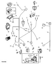
Start-Up Lockout (P7 SPDT switches for three wire control and can be wired Murphy Industrial Harness2 or John Deere OEM engine. Rack Pullers. Pull/Push DC Solenoids for Diesel Engines — RP Series. SPDT switches for three wire control and can be wired to make or to Diagrams are shown in the shelf position with no force acting Direct connect with Murphy Industrial Harness or John Deere OEM engine harnessing.
Wire diagram for most B&S engines
How to Order. Rack Pull Solenoid. (RP Series Wire. MS MS 6.
2. 3. 1.
6. 2 .
Member Log In
3. 1.
Typical Wiring Diagram with /PH Magnetic Switch. Typical.Subject: Wire diagram for most B&S engines Wed Apr 03, pm This wire diagram will work for a big majority of Lawn Tractors with a B&S engine. This is the wire set up i .
Install, Wire & Troubleshoot FW Murphy W-Series Engine Panels. Typically this panel will control the ignition coil, an inline fuel valve or a push/pull solenoid for shutdown. NOTE: This is an immediate shutdown device, typically used on stand-alone engines.
Rack Pulls – Back Exercise – schematron.org
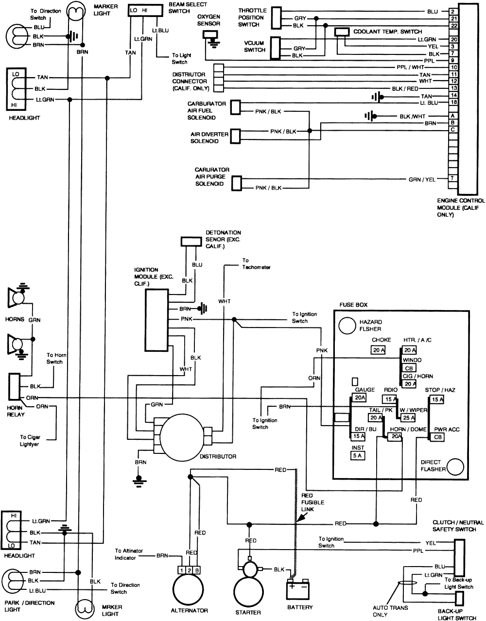
(Murphy MEN) Wiring Diagram – . Rack Pull Solenoid (RP Series shown) Tachometer Hourmeter Voltmeter 20T Temperature 20P Pressure Ammeter Battery + _ + _ + _ ST ACC IGN BAT Start Switch Alternator To Magnetic Sensor, Alternator “Tach” Terminal, or Signal Generator B + Energized to Run PBS Stop Switch Starter S B Exciter R Fuel Valve Typical Wiring Diagram with A.
Solenoid Wiring. Does it matter what wires go where?
Dec 05, · 1. From your controller, run the wire that comes out the back of it to the small post on the right. 2. Then take a 3″ wire and run it off the small post on the left to the ‘BAT’ big post on top.
3. Then run the positive cable coming from your pump to the big post on the bottom. 4. Typical Wiring Diagram with A and APH G NO R NC SW1 SW2 B PH Jumper* B + SIG GRD + _ Distributor Ignition coil Fuel Valve Rack Pull Solenoid (RP Series shown) Tachometer Hourmeter CLOSEDLOOP™ Wiring* Voltmeter 20T-F Temperature 20P-F Pressure Ammeter Battery + _ + _ + _ ST ACC IGN BAT Start Switch Alternator To Magnetic Sensor.Deutz-Fuel Shut Off Solenoid replacement? – Page 2Install, Wire & Troubleshoot FW Murphy W-Series Engine Panels