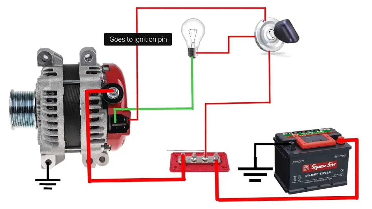
Start by understanding the specific configuration of the four terminals, which allow you to integrate multiple power sources into a unified setup. Each terminal has a unique function, and proper identification is crucial to avoid errors in your connections. Check your components’ specifications before proceeding.
Begin with the primary terminal, which handles the core power output. This should be connected to the positive lead of your power distribution system. Ensure the connection is secure, as this will be the main pathway for the energy flow. Use a durable connector for reliability.
The secondary terminal is often responsible for ground or reference connections. A stable ground is essential for the consistent operation of the entire unit. Connect this terminal to the ground point, ensuring the wire is properly shielded to prevent short circuits or interference.
The third terminal often serves to regulate voltage or current. For systems requiring precise control, this terminal needs to be connected to a controlling unit or voltage regulator. Check the manufacturer’s instructions for specific voltage requirements to maintain optimal operation.
The final terminal may be used for additional functions, such as monitoring or signaling. If your system includes a feedback loop or a control mechanism, this terminal should be connected accordingly. Always verify that the wire gauge and type match the expected load to ensure long-term reliability.
Ensure all connections are properly insulated and follow safety protocols to avoid damage or malfunction. Double-check each connection before activation to prevent issues during operation. Testing the system once all connections are complete is highly recommended to ensure everything functions smoothly.
Connecting a 4-Terminal to Single-Line Generator Electrical Setup
To simplify the connection of a four-terminal electrical source to a single-line output, ensure the following steps are followed carefully:
1. Identify the main terminal that serves as the power output and connect it to the primary load. This terminal typically carries the main voltage and is critical for consistent energy delivery.
2. The second terminal, commonly used for sensing or regulating, should be connected to the control circuit that manages voltage levels. Proper connection of this terminal is necessary for maintaining system stability.
3. The third terminal may serve as a ground or return path. It is important to securely attach it to a solid ground point to ensure safe operation and prevent electrical surges.
4. The fourth terminal often acts as a signal or communication link. Ensure it is connected to the appropriate monitoring equipment if the system is equipped with such functionality.
When joining these components, use a high-quality, durable conductor to prevent power loss and ensure efficient operation. Additionally, double-check each connection for stability and accuracy before initiating the system.
Step-by-Step Guide for Connecting 4-Terminal to Single-Wire Generator

Start by identifying the four terminals on the generator and the corresponding single-wire setup. The first step is to connect the main power terminal to the vehicle’s battery positive terminal, ensuring a solid connection to prevent any voltage loss.
Next, connect the ground terminal directly to the vehicle’s chassis or battery negative terminal. This will complete the circuit for proper grounding.
For the third terminal, which regulates charging, run a wire to the voltage regulator or to the engine control unit depending on the system configuration. This ensures proper charging control and monitoring.
The fourth terminal, often used for signal purposes, should be linked to the vehicle’s electrical system for monitoring or other functions. If not required for the specific setup, this terminal can be left unconnected, but it’s crucial to ensure it’s safely insulated if not in use.
Once all terminals are properly connected, double-check for any loose connections or exposed wires. Tighten all terminals securely and insulate any exposed sections of wire to prevent short circuits.
Finally, test the system by starting the engine and checking the voltage output to verify everything is functioning correctly. A stable voltage reading indicates a successful setup.
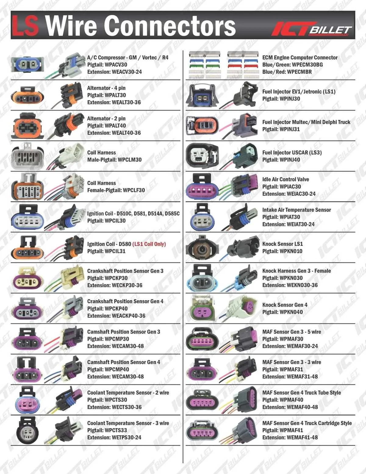
Identifying and Understanding the Pinouts in LM7 Electrical System
For proper function, it’s crucial to identify and understand the electrical connections in the LM7 unit. Below are the key components to focus on:
- Terminal A: This is the primary connection responsible for power output. It’s vital to ensure a solid connection here to avoid performance drops.
- Terminal B: Often linked to the ground or negative supply. Verify continuity to ensure proper grounding and avoid potential electrical interference.
- Terminal C: Typically used for signal communication with the system’s control unit. Check for any loose or damaged connections that could lead to faulty operation.
- Terminal D: Acts as the voltage regulator input. Ensure this connection is free of corrosion or wear to maintain the unit’s efficiency.
For optimal functionality, always use the correct gauge wire and ensure all connections are free from oxidation or damage. Regular inspection can prevent common issues such as insufficient output or erratic performance.
Common Connection Issues and How to Troubleshoot LM7 Electrical Setup
1. Loose or Corroded Terminals: Ensure all connections are tight and free of corrosion. Clean terminals with a wire brush and apply dielectric grease to prevent future buildup.
2. Poor Grounding: Check that the ground connection is secure. A loose or faulty ground can cause electrical interruptions. Use a multimeter to test continuity between the ground and the negative terminal of the battery.
3. Faulty Voltage Regulator: If voltage is inconsistent, the regulator might be malfunctioning. Use a voltmeter to check output voltage. It should read around 13.5 to 14.5 volts when the engine is running. Replace the regulator if readings are outside this range.
4. Damaged Fuses or Fusible Links: Inspect the fuse or fusible link for visible damage. A blown fuse can break the circuit and disrupt power. Replace any damaged fuses or links with the correct amperage rating.
5. Broken or Worn-out Wires: Over time, wires can degrade or break due to wear and tear. Inspect all visible wires for cuts or abrasions. If necessary, replace damaged sections with properly rated cable.
6. Misalignment of Connectors: Ensure all connectors fit properly without resistance. Loose or misaligned connectors can prevent proper voltage transmission. Disconnect and reconnect each connector to check fitment.
7. Overheating: Excessive heat can damage the electrical components. Check for signs of melting or discoloration around the components. Ensure adequate airflow around the setup to prevent overheating.
8. Inadequate Charging Performance: If the system isn’t charging correctly, test the system with a multimeter while the engine is running. If the voltage drops below 13.5V, investigate potential issues with the power delivery path or electrical components.