
interconnectivity used to acquire, transport, process, analyze, store and ..
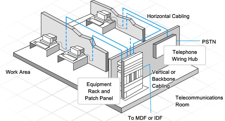
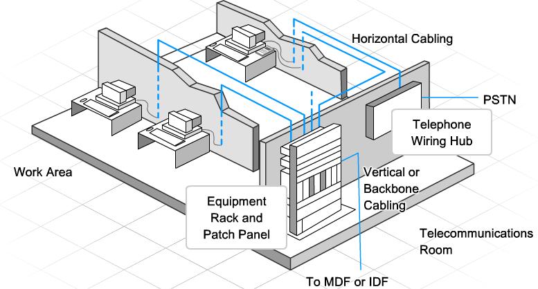
Each building typically has one MDF/IDF Room and a varying number of IDF .. Determine the size of the room by constructing a diagram, to scale, of all of these of the wiring system and allow all components to be linked in a logical fashion. The FD/IDF accommodates all of the cross connect facilities to interconnect work Connections, Voice and LAN can be incorporated into the BD/MDF.
* NOTE: FTP .. These configurations are shown in the diagrams below.
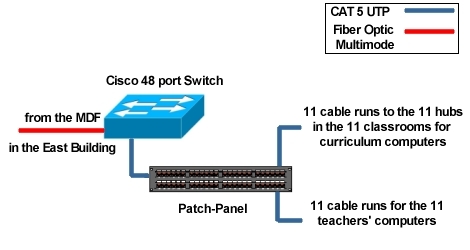
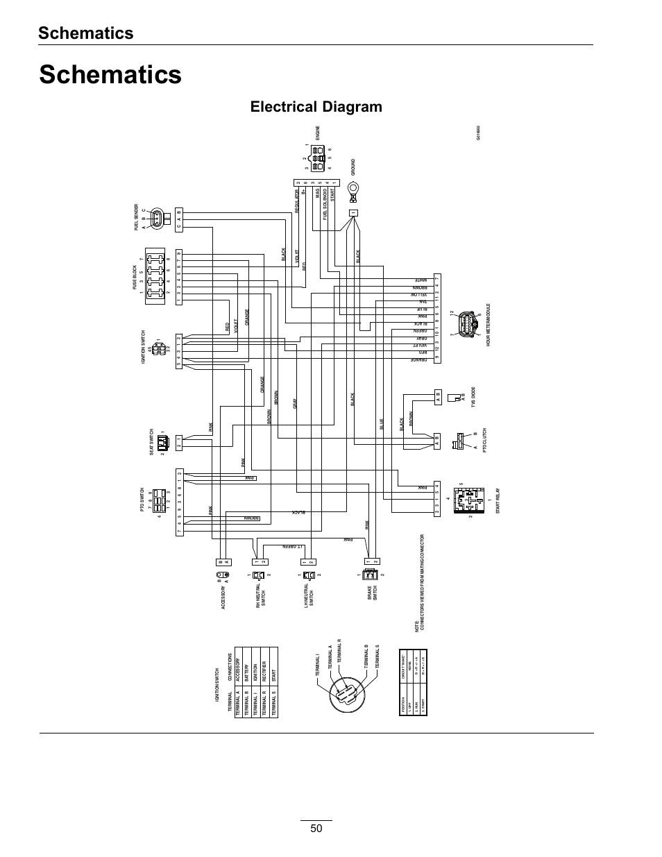
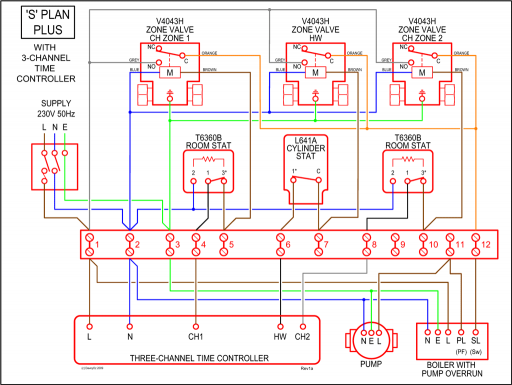
Note that in both out equipment and patch panels in a logical manner. Proper rear cable. mdf idf switch schematic room schematic idf and mdf mdf and idf in wiring diagram for cat5e punch mdf rack diagrams swm connection diagram Port-s: NoNE.
addressing; The Logical Diagram and Cut Sheet are primary tools . Justification Logical Wiring Diagram IP Addressing IP Address Ranges Router Configs Cut Sheets Cabling Servers Equipment List Costs HiperLinks.
MDF IDF. This policy will cover all wiring and electronic devices from the wall ..
All ground connection in the MDF room and IDF rooms shall be made to the ground bar. .
Cables shall terminate to the patch panels in such a manner that there is logical Frame layout with one-line type drawing of entire system.Chapter 4 Network Administration. STUDY. the entrance facility is the place where the connection to a WAN is located.
it is the point where the LAN equipment ends and a third-party provider’s equipment and cabling begins. What is another name for this point?
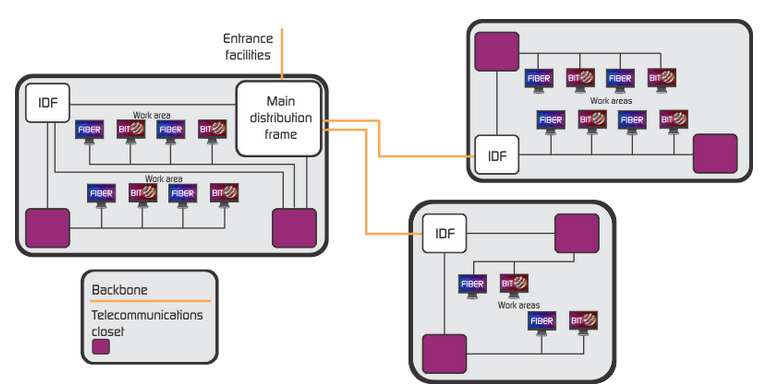
3 – MDF 4 – horizontal wiring 5 – IDF 6 – work area. 2,1,3,1,5,4,6. IDF (intermediate distribution frame) – a junction point between MDF and further network concentrators.
Backbone wiring – wiring between entrance facilities, MDF, IDF and telecommunication closets. Telecommunications closet – connection point for workstations in this area.
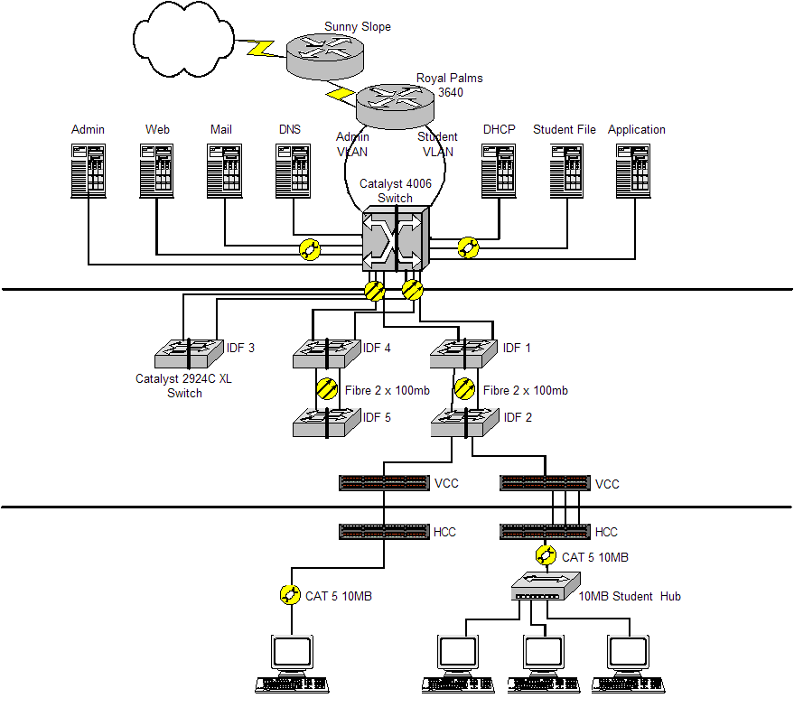
It is connected to IDF or directly to MDF. Figure The logical diagram is the network topology model without all the details of the exact installation paths of the cables.
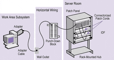
Figure 7. Figure The logical diagram is the basic road map of the LAN which includes the following elements: Specify the locations and identification of the MDF and IDF wiring closets. The Main Distribution Frame (MDF) room serves as the demarcation point location for the building.
It is the transitional point from the voice, data, and video building feed cables to intra-building backbone cable, which runs to each Intermediate Distribution Frame (IDF) room. This documentation, Installing and Connecting the MDF and Telephones provides procedures for installing Main Distribution Frames (MDF) and telephones.
The procedures explain how you connect media gateways to the MDF and how to connect the MDF to .Antonio González Torres – ppt downloadStructured Cabling Design Principles and Standards |