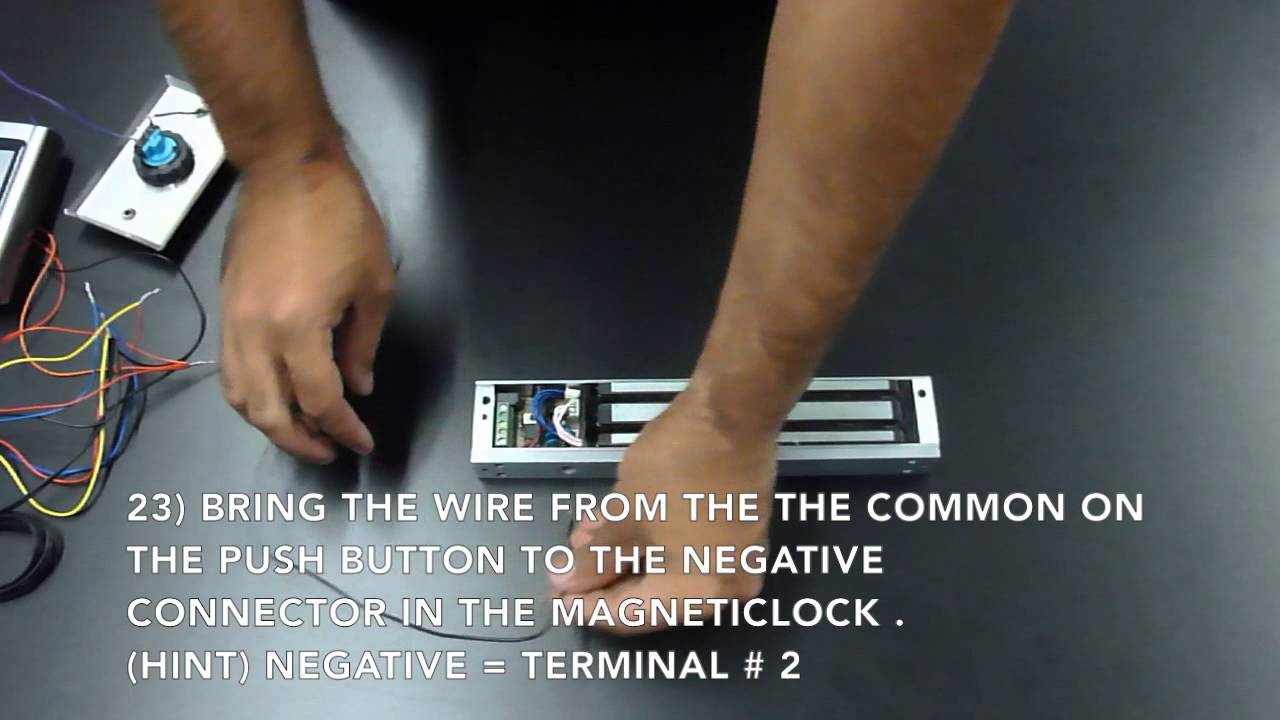
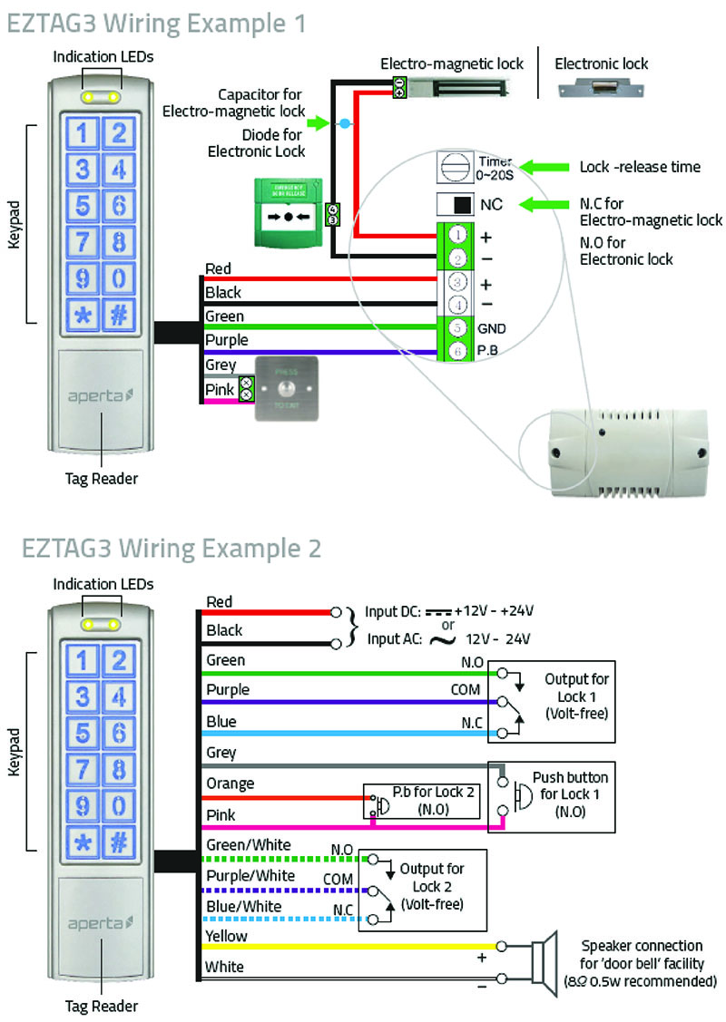
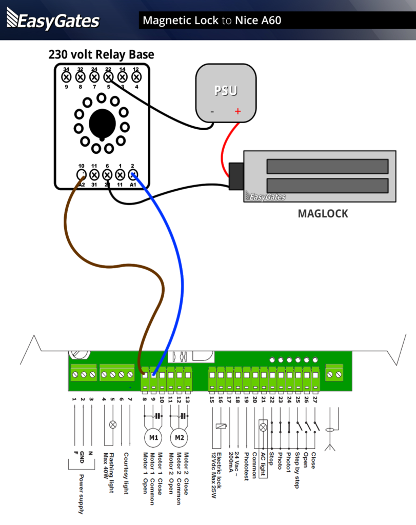
Lock Power Supply. Adapter that supplies power to the magnetic lock Figure 3: Diagram from the manual that shows where to connect wires. Larger diagram.
Lock Power Supply. Adapter that supplies power to the magnetic lock Figure 3: Diagram from the manual that shows where to connect wires.
Common wiring diagrams
Larger diagram. Magnetic Lock Installation & Support. Mag-Lock w/ Push Buttons.
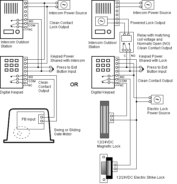
Wiring Diagram for Mag-Lock w/ Push Buttons Wiring Diagram – Biometric & Push Button. It is essential that the surfaces of the armature and the magnetic lock seat perfectly to one Maglock.
Mounting. Bracket.
Weld to fence post. (Typical connection).
Common wiring diagrams
The following common wiring diagrams are available: Standalone with access control and Magnetic Lock · Wireless Multi-Technology Reader – GCK> Magnetic Lock Setup Guide Diagram from the manual that shows where to connect wires. Larger diagram In this example, the manual labeled the blue wire leaving the 6-pin connector as the negative connector to the magnetic lock. The wire we actually use for the connection is the green one that extends past that blue wire and the power. Maglocks can be used on hollow metal, wood, aluminum, glass and composite door materials.
The UL Listed Maglocks are available in surface mount single or double door configurations, with holding force of or 1, lbs.
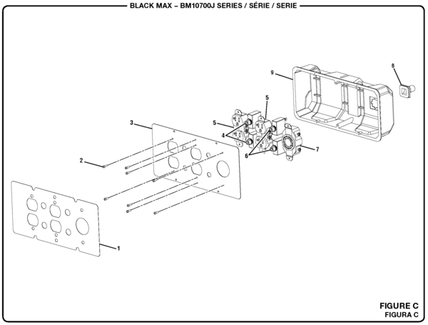
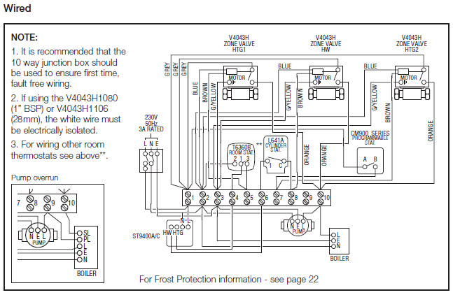
These locks include adjustable sec relock time delay and a . wiring diagram request form. Common Wiring diagrams.
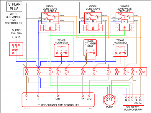
wiring diagram for QEL panics mag lock wiring diagrams. chexit wiring diagram.
lever locks for fire doors. emergency release tool.
two single doors with panic bars. two single doors with panic bars.
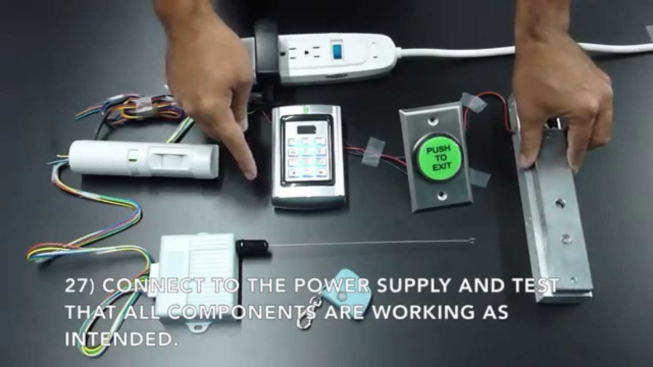
push button release electric strike. – WIRING INSTRUCTIONS— magnetic lock or fail safe strike with button, keypad and PIR wired in series Power Supply for fail safe strikes and magnetic locks should be DC.
If this is not available you may use an AC power source and wire inline a “Full Wave Bridge” rectifier. This will conver t the AC to DC.
LiftMaster LA Residential DC Linear Gate Operator User Manual • Wiring diagram + diagnostic codes, Wiring diagram diagnostic codes, Gate 1, Gate 2 • LiftMaster Safety.Common wiring diagramsBasic Magnetic Door Lock System | HubPages