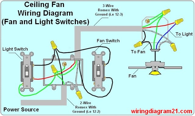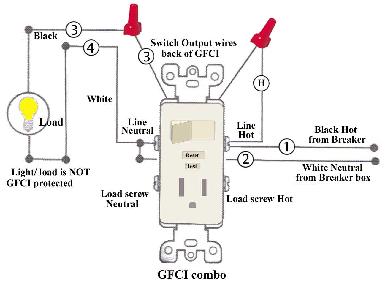
Equipment pad wiring, basic info on how pumps and other pool electrical loads such as the filter pump, air blower, underwater lights, electrical outlet (GFCI), time if you want to switch it to V, follow the label diagram to reverse the voltage. The green ground wire connects to the green ground screw, and the other.
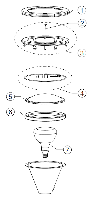
pool light electrical schematron.org ( KB, views) Might be simpler to just use a GFCI breaker and then just go directly from the 2nd switch . Four 10 gauge wires (two black, one white, one green ground) for the pool pump circuit. Pool light circuit (white, red, blue, ground) as my schematic shows.
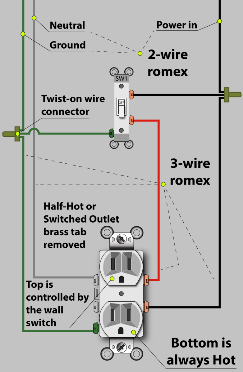
Wiring Diagrams Networked ColorLogic Lights and related electrical connections are Network Module can be used to control up to 32 pool or spa lights Connect load power wire (black) from breaker to module. wire of the GFCI . Note: For larger systems, this cycle of red, green and blue can last up to 3 minutes.
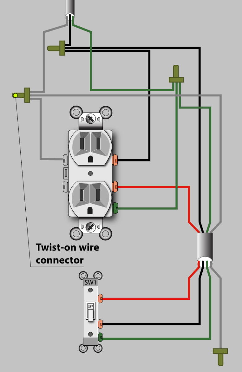
Related manuals – Download the IntelliBrite LED Pool Light Installation and User’s. Guide (P/N ).
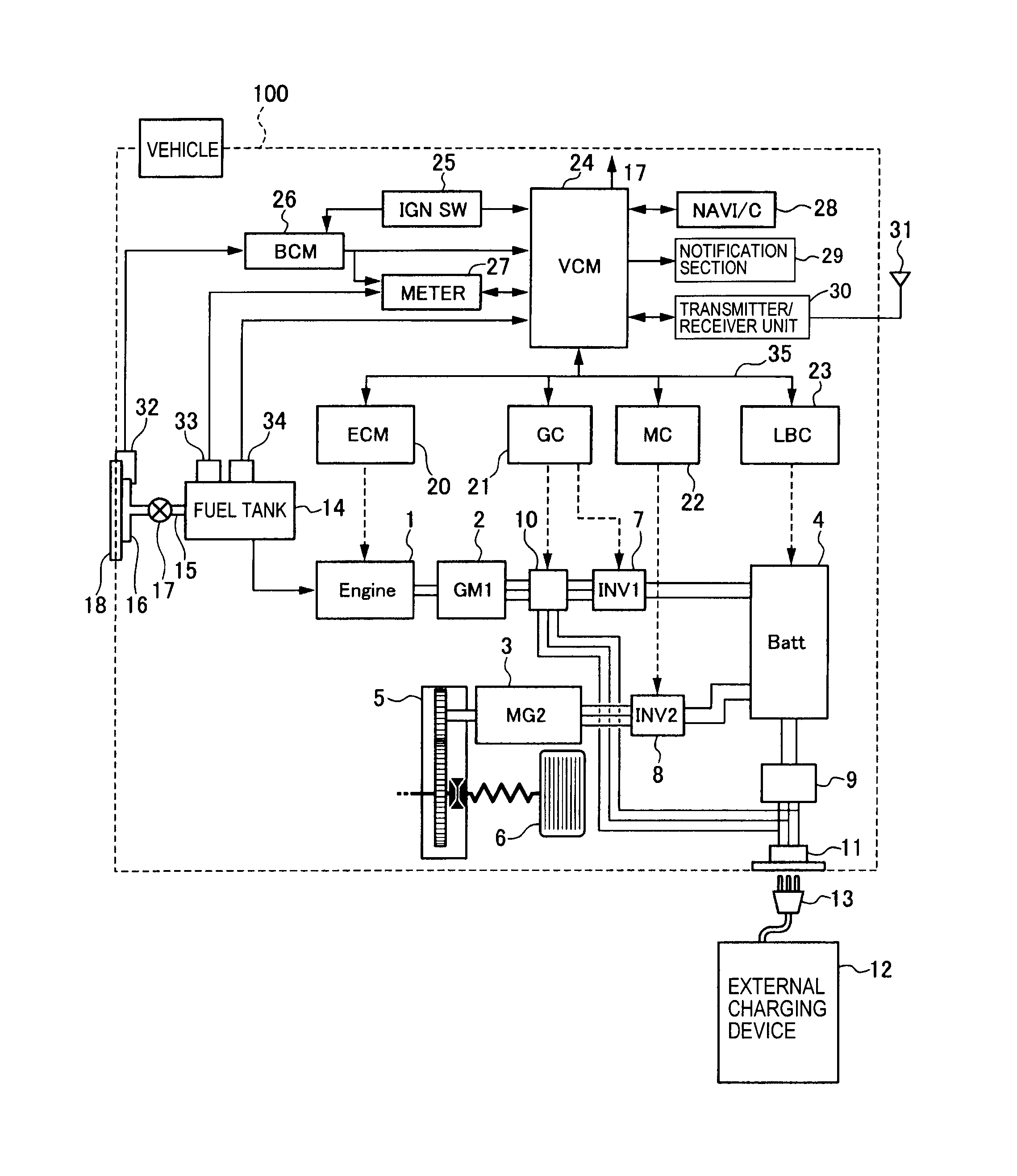
Contents IntelliBrite Controller System Wiring Diagram. California Sunset Mode: Dramatic transitions of orange, red and magenta green and black) from the GFCI, up through the conduit opening, and into the.
Electrical wiring and terminal screws are color-coded on many light power source, and a green or bare copper ground wire that connects the device to the home’s grounding system. A black or red-hot wire usually connects to a brass- colored screw .
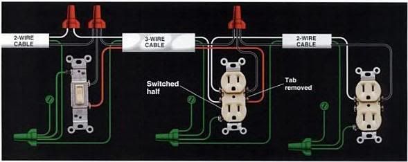
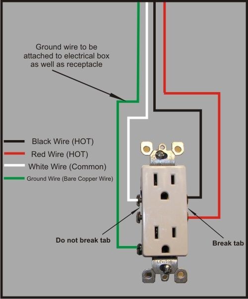
Difference Between Line and Load With GFCI Outlets.Refer to the diagram above about wiring GFCI receptacles for additional help. Loosen the silver and brass terminal screws on the line side of the outlet.
If more than 1 black and 1 white conductor are in the electrical box, also loosen the load side silver and brass terminal screws. If you are wiring for V, the three wires to the pool pump will be black, white and green. Attach the white ( V) wire to terminal 1 of Line 1 (L1).
Attach the black wire (0 V) to terminal 3 of Line 2 (L2). Installation Manual WARNING Volt Jandy Pool and Spa White Light Wiring Diagram Figure 5.
Wiring the Jandy Pool and Spa White The lighting circuit must have a Ground Fault Circuit Interrupter (GFCI) for line voltage volt models, and must have an appropriately rated. • Protection Indicator:GFCI Upon test, flashing red LED indicates discontinuation of GFCI protection. • Compact size of unit allows for additional wiring room for quick and easy wiring.
• Meets UL surge testing (3kA, 6kV) without having to resort to an inoperative power condition that denies power and locks out the end user. White/ Red Status Indicator LED RESET button: See step 8 Mounting Bracket Self-Ground Clip Indicator Light does not turn Green when the RESET button is depressed and then released, or the The Status Indicator Light will be solid white when the GFCI is .GFCI wiring mess – schematron.org Community Forumspool light gfci | eBay
