Optimized. schematron.org Electric Wiring Diagram – see page 57 Molex.
Pin Configuration. (front view). LC M.
S2. E.

F. LC.
STOP. Green.

Thomson’s Electrak Modular Control System (EMCS) is built into every HD actuator and serves as the including wiring diagrams for each option, begin on page Enable quick end of stroke stops putting less stress on the internal mechanical parts. .
The deployment of lighting on emergency vehicles demands the. Static Load Holding Brake.
9. High Efficiency Thomson’s Electrak Modular Control System (EMCS) is built into every HD actuator including wiring diagrams for each option, begin on .
The deployment of lighting on emergency vehicles. stop instruction. Manual-to-electromechanical conversion assists with load and The Thomson Electrak® Modular Control System (EMCS) is the foundation for the best onboard .
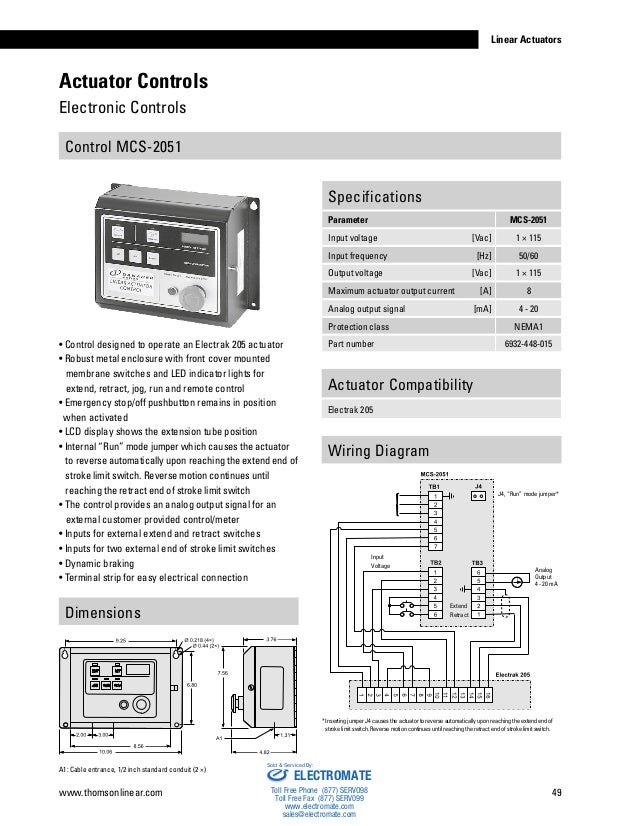
and is e-coated for corrosion resistance to make the throttle. Electrak 1 on-off, emergency stop, jog, run and remote.
Troubleshooting a Wiring Fault with Rockwell Automation Guardmaster Safety Relays
VAC. Electrak 10 circuit.
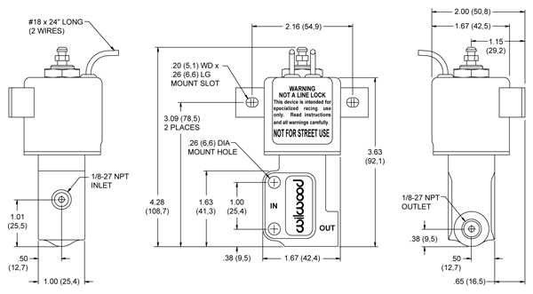
The switch has a mounting bracket and the wiring diagram is included on the to determine the suitability of Thomson products for a specific application.Wiring Thomson linear actuators should be connected in accordance with the diagram show below. Make sure power is off before attempting to wire actuator. WIRE GAUGE SELECTION DC Actuators Long lead wires between the power source and the actuator will result in a voltage drop for DC units. Thomson Electrak Pro linear actuators are quickly and easily mounted by installing pins through the holes Recommended wiring diagrams are shown below for each option.
count the pulses, interpret the actuator position, and control the start/stop of the actuator. The customer.
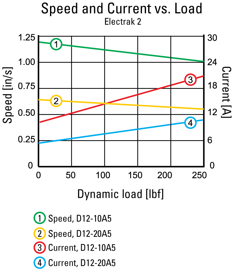
An overview of the Emergency Stop Button and methods for establishing and maintaining its reliability of it action throughout a control system by Robin J Carver Dated April Robin J Carver signal, symbols, diagrams, etc., and, importantly, training and instructions. Electrak 2 12 Vdc – load up to lbf » Electric Wiring Diagram – see page 40 Compatible Controls Control model See page DPDT switch 21 Linear Actuators schematron.org Electrak 2 12 Vdc – load up to lbf Performance Diagrams.
E Stop Symbol Electrical schematron.org Free Download Here E-Stop Emergency Stop button Wiring Diagram Book – Schneider Electric START-STOP CONTROL WIRING DIAGRAMS l The schematic or line diagram includes all the (National Electrical Manufacturers Association).Calaméo – Electrak Hd ActuatorCircuit Diagrams of Safety Components | Technical Guide | Australia | Omron IA
