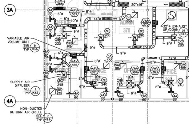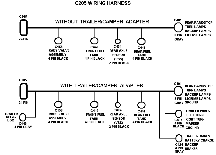
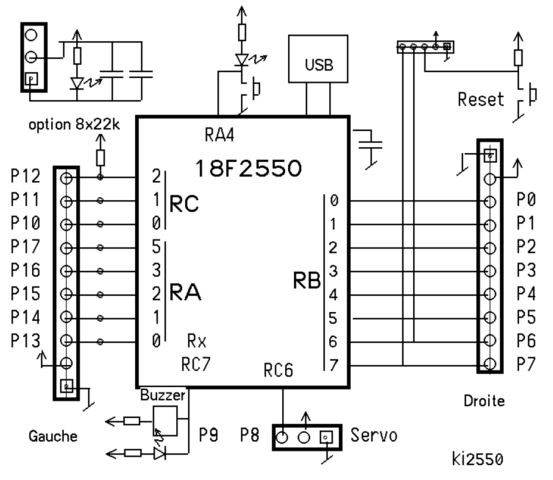
Wiring the VAV Zone Controller to the MS/TP network.

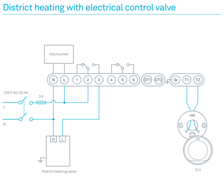
.. Wiring diagram legend . Modulating hot water (ducted or baseboard) – Fan box application.
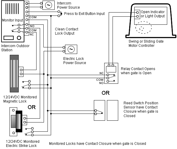
Tim’s Tech Tips: 06 – Controlling a VAV box with a Pneumatic controller – Duration: ControlTrends Smart Buildings 25, views · Common practice in VAV box control is to use the control logic depicted in .. approach since at peak heating (the far left side of the control diagram), both. Wiring the VAV Zone Controller to the MS/TP network.
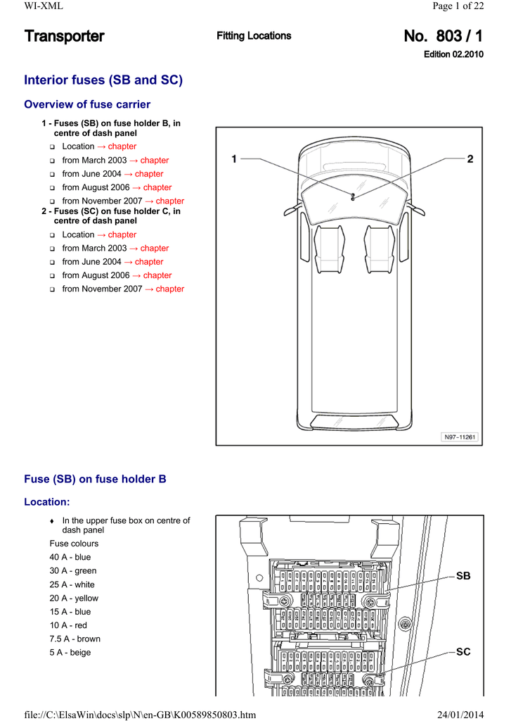
.. Wiring diagram legend .
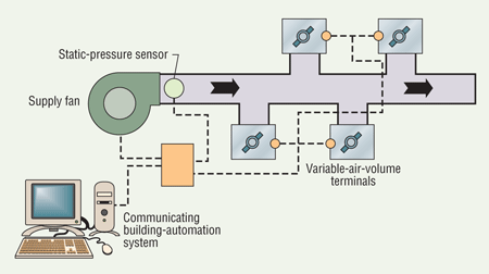
Modulating hot water (ducted or baseboard) – Fan box application. Cause-effect Diagram for the VAV-box Flow Rate Differing from Normal Self- Correcting Controls for VAV System Faults Filter/Fan/Coil and VAV Box Sections.VAV Controller—Variable Air Volume (VAV) Controller 9 In conjunction with the mechanical contractor, the controls contractor’s responsibilities include: 1. Coordination of the control system release schedule to the box manufacturer to ensure the mechanical system delivery schedule can be met.
PRECISE ZONE CONTROL Model SDR terminals provide variable air volume (VAV) control beyond the typical single duct box. They are specifically designed for precise air delivery throughout the entire operating range, regardless of the installed inlet conditions. They also offer improved space com-.
NECC offers Variable Air Volume controls, VAV boxes, VAV terminal units and controllers from Nailor, KMC, Kreuter, Johnson Controls. Variable Air Volume control / VAV box factory authorized distributor, with same day shipping from stock.

INTRO TO CONSTANT VOLUME AND VAV SYSTEMS VAV System OA Damper Control Minimum Air – AFMS M M M Minimum Air Control: Control to Maintain OA-AFMS Setpoint Outside • Can be Reset Based on VAV Boxes % 75% 35% 62% Speed = . 2.
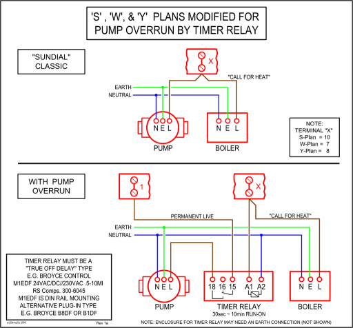
Follow the wiring/piping diagram found on the side of the unit or the inside of the electric heater control panel cover. 3.
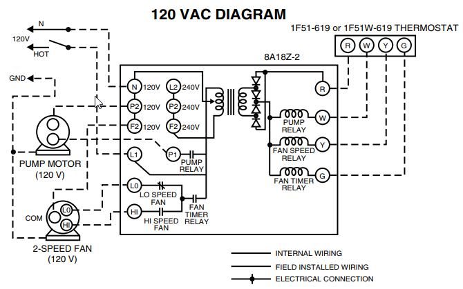
Supply connections must be made using wires rated for 75°C minimum. DO NOT USE ALUMINUM CONDUCTORS.
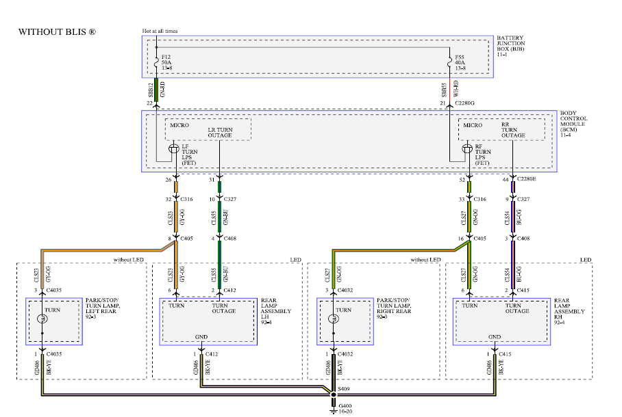
4. If supply connections are for volts or greater, all wiring must be insulated for V. 5.Hvac Systems new: Vav Hvac SystemVariable air volume – Wikipedia
