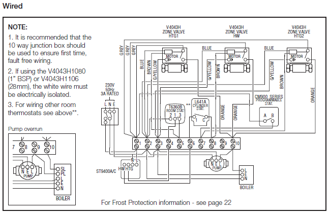
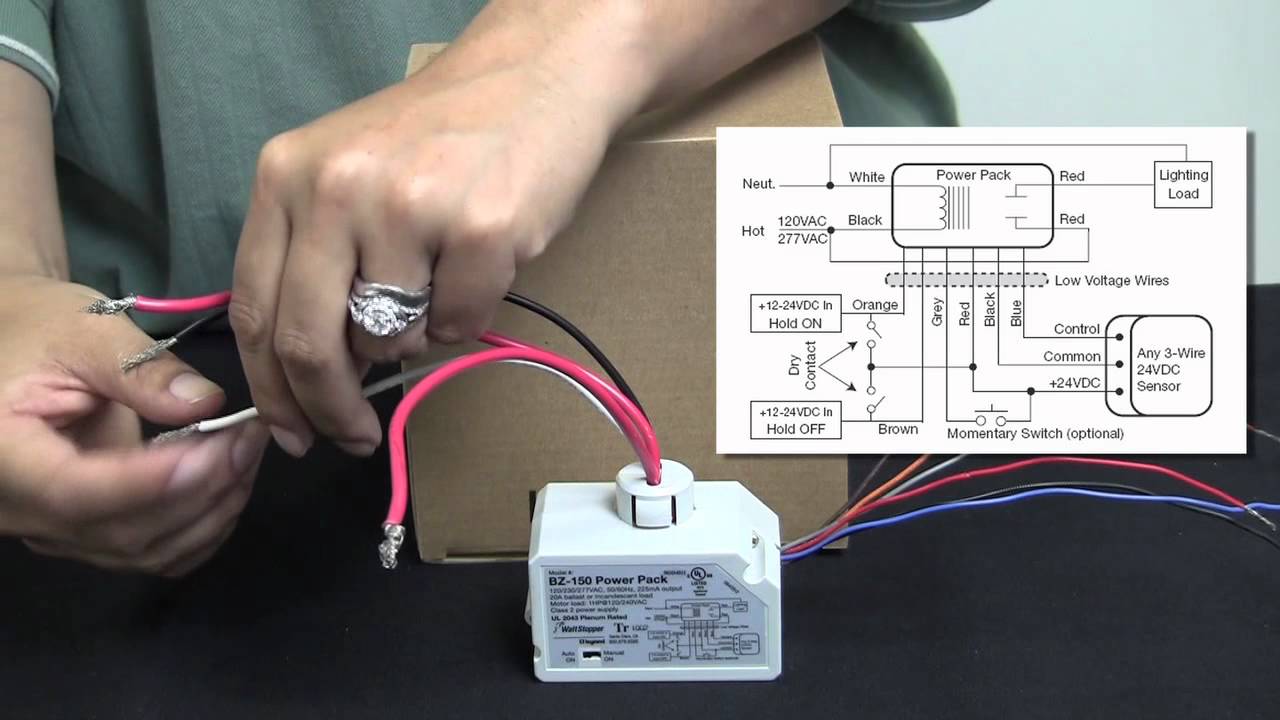
can provide 24 VDC operating voltage to Wattstopper’s low- voltage occupancy 14 AWG wires on the relay for 20A operation Installation Diagram. Wiring.
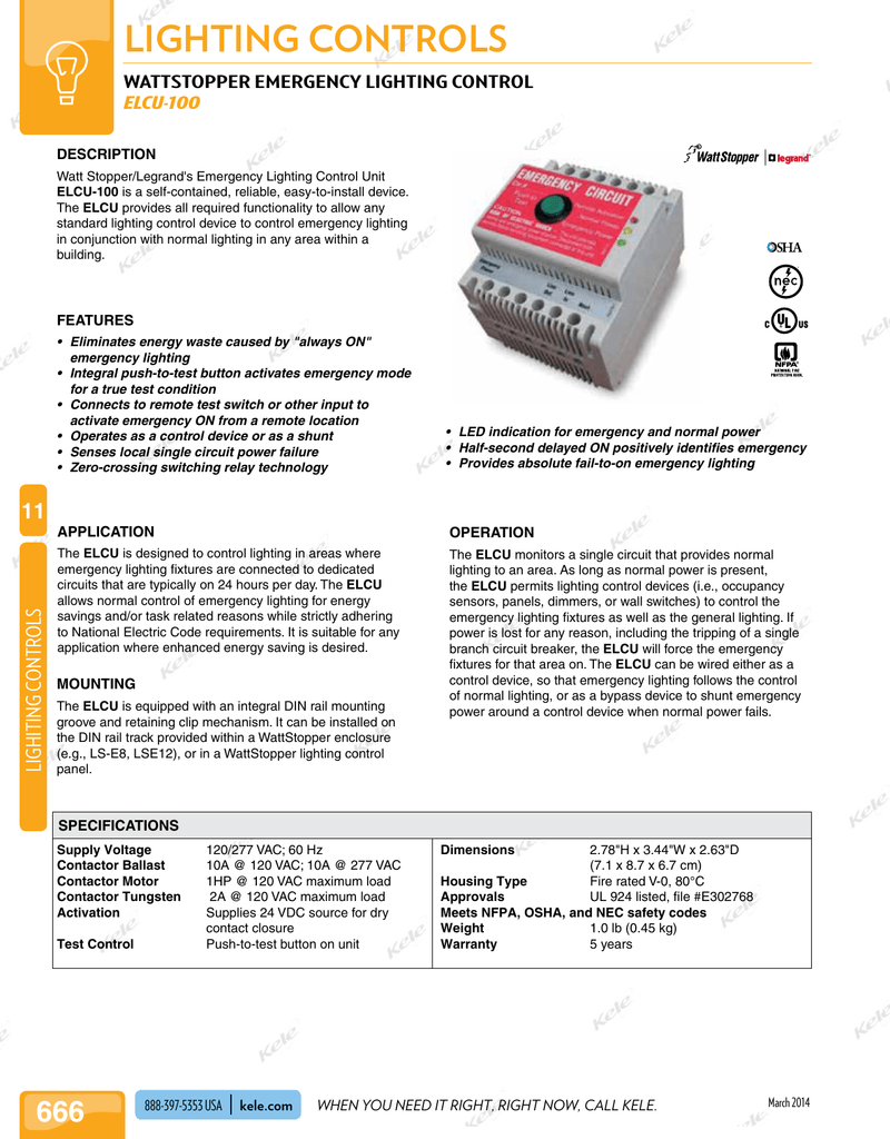
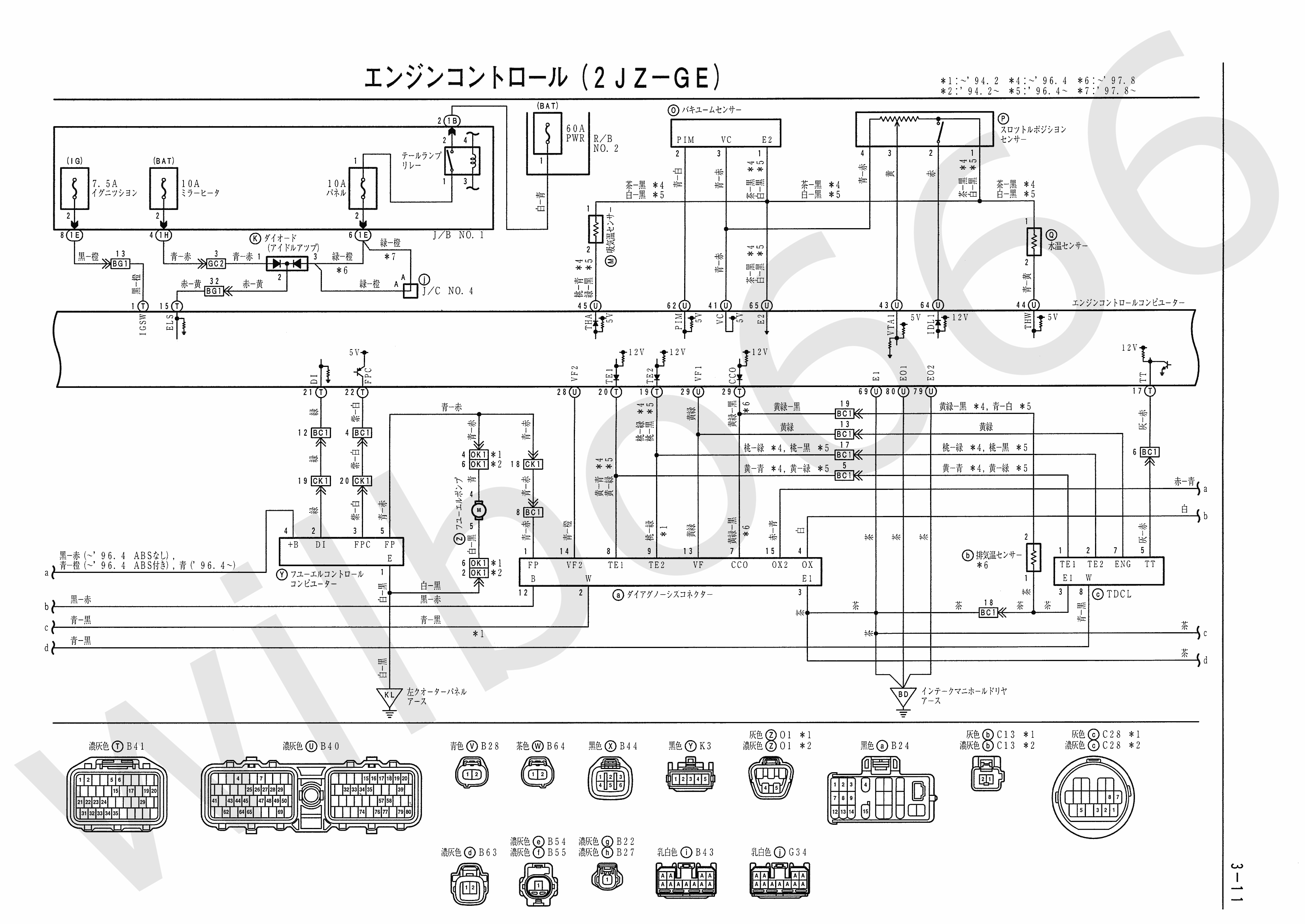
Diagram is typical for space type. Provide proper quantity topology wiring arrangement to connect lighting control devices.
4. schematron.org wattstopper. Fof the product, see the DLM System Installation Guide at.
schematron.orgopper. com. WattStopper.
Title. LMRC– Triple Relay.
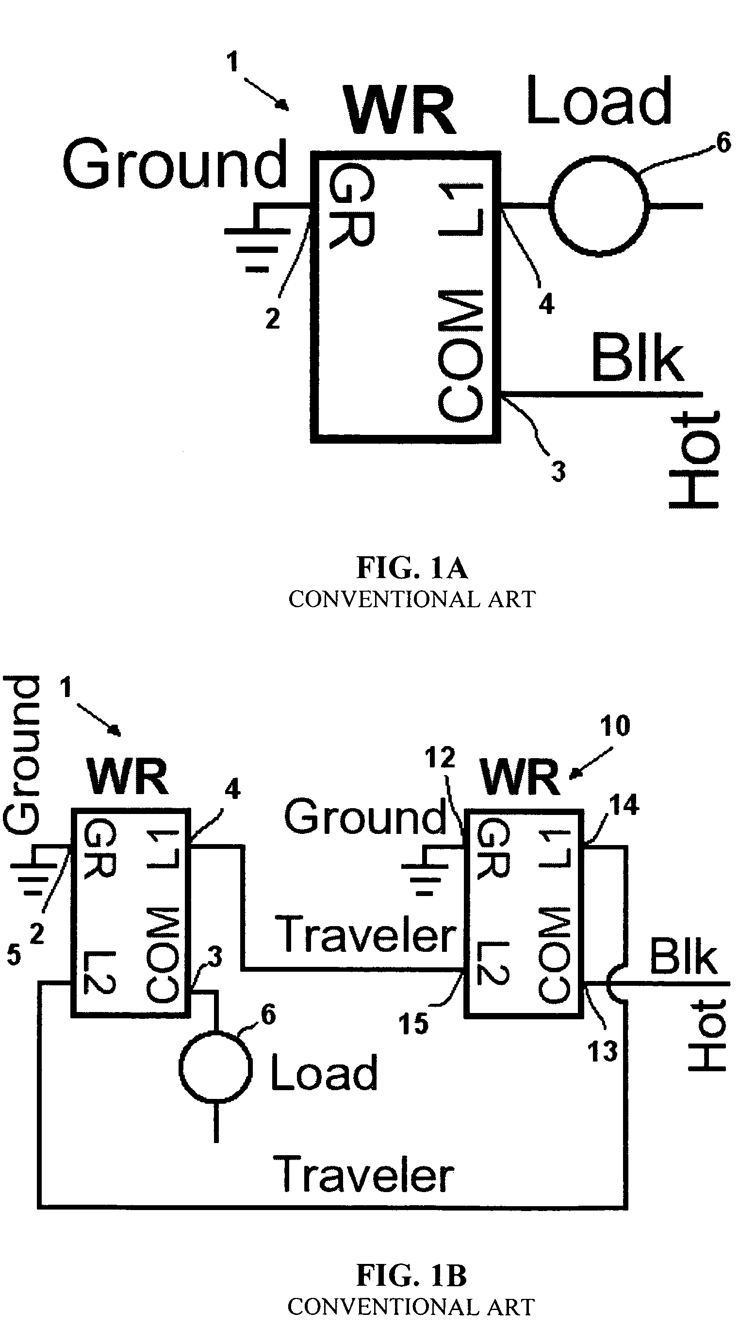
Wiring Diagram . Connect the line voltage and load wires to the power pack leads as shown in the Wiring Diagram for the unit’s application.
• Do not allow bare wire to show. Visit our website for FAQs: schematron.org Walk-Through. The Walk- Through wiring diagram that is appropriate to the PW model and electrical supply.Wattstopper’s ELCU Emergency Lighting Control Unit is a self-contained device that allows any standard lighting control device to control emergency lighting in conjunction with normal lighting in any area within a building.
schematron.org DT Dual Technology Ceiling Sensor PROJECT LOCATION/TYPE • Advanced control logic based on RISC microcon-troller provides: Wiring Diagram DIP Switch Settings Ceiling Mounting Product Controls . View and Download Wattstopper DT installation instructions manual online. Dual Technology Line Voltage Occupancy Sensor with Light Level feature.
DT Accessories pdf manual download. Wattstopper Wiring Diagram – Is it a Scam? To remove you must slide the plug to the outside of the vehicle, then it can be gently removed.
Depending upon the sort of box you’ve purchased, it can or may not arrive with built-in connectors. Watt Stopper/Legrand’s Emergency Lighting Control Unit (ELCU) is a self-contained, emergency lighting control device.
The ELCU provides all required functionality to allow any standard lighting control device to control emergency lighting in con-junction with normal lighting in .Wattstopper Wiring Diagrams | Wiring LibraryWattstopper Wiring Diagram Pdf – Circuit Diagram Maker