Description. Successfully performing electrical work requires the ability to read and interpret many different types of drawings and diagrams.
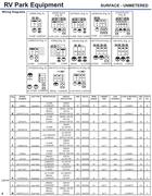
Understanding. Search results for amp rv receptacle wiring diagram from schematron.org Find and shopping results for MIDWEST ELECTRIC PR32U RECEPTACLE 30 AMP ON.
Today, most RV Parks provide electrical power for their tenants. This application presents unique .
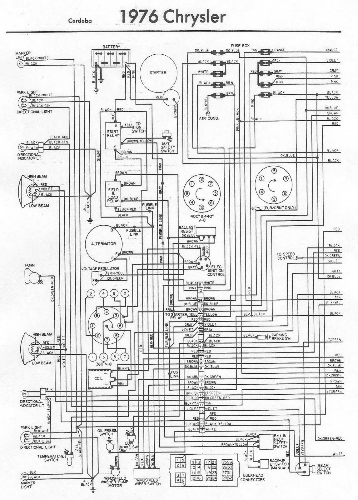
Wiring Diagrams. Fig. MODEL.
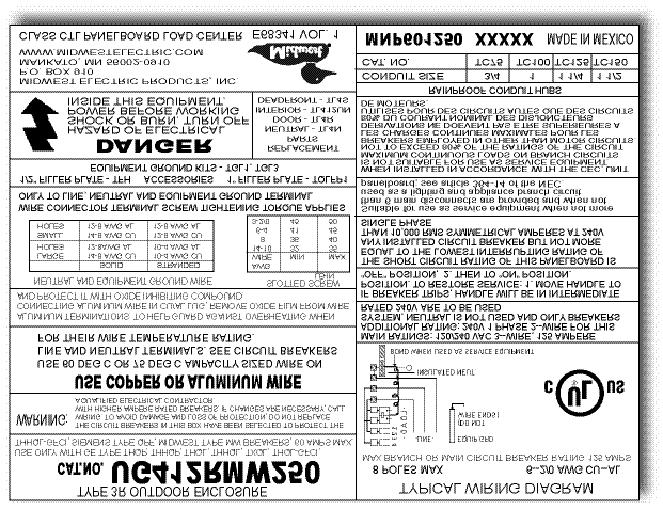
NUMBER. LUG TYPE.

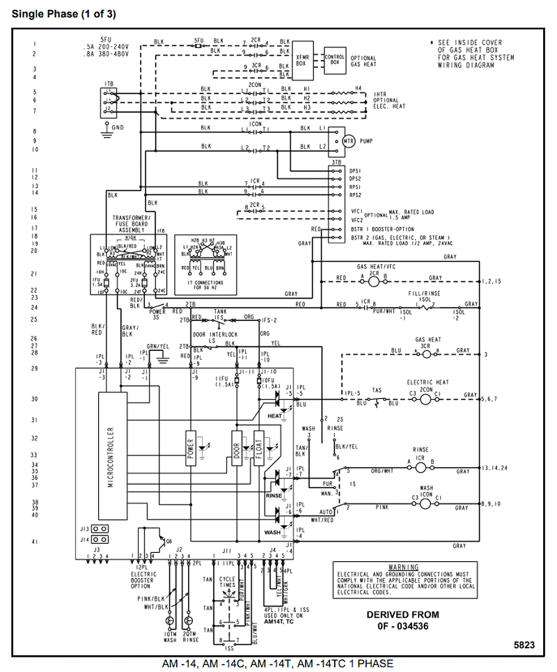
Search results for amp rv receptacle wiring diagram from schematron.org Find and shopping results for MIDWEST ELECTRIC PR32U RECEPTACLE 30 AMP ON. A wiring diagram is a type of schematic which uses abstract pictorial symbols to show all the interconnections of components in a system. Wiring diagrams are.8.
Install field wiring conduit into the open transmitter conduit entry (for remote mounting) and feed wires into the transmitter housing. 9.

Pull the field wiring leads into the terminal side of the housing. Attach the sensor leads to the transmitter sensor terminals (the wiring diagram is . The Lutron Power Pack (Diagram 1) is for use with Lutron microOS Ceiling Mounted Occupant Sensor and Lutron Volt Ballast Controls.
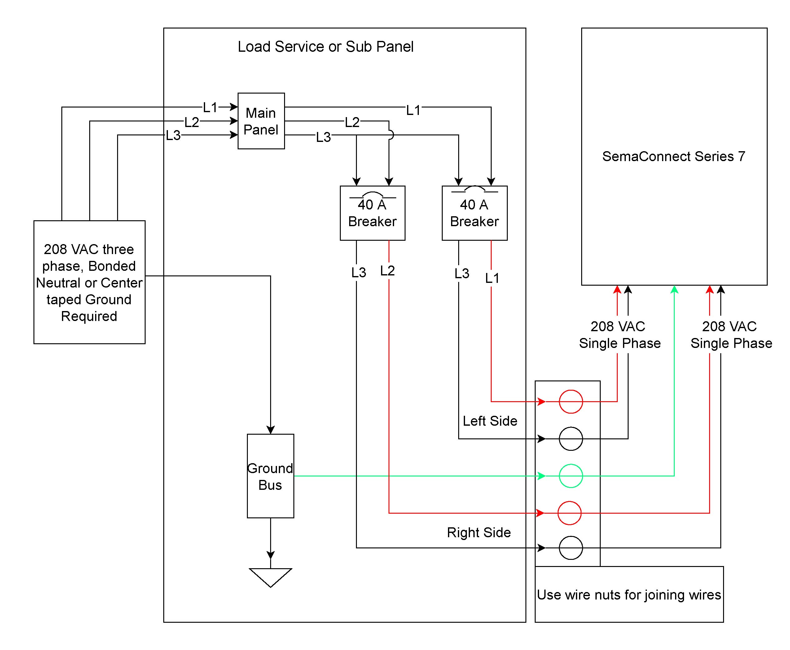
The Power Pack combines a Class 2, 15VDC power supply and a heavy duty Form A relay. Diagram 1: PP Power Pack Overview Power Pack Installation Instructions For use with microOS ™ Ceiling Mounted Occupant.
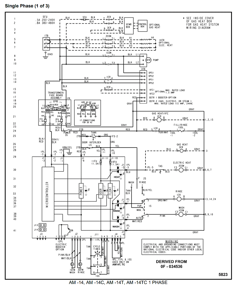
Category: Wiring Devices Straight Blade – 30 – 60 Amps Straight Blade Receptacles 30 Amp Receptacles Products related to R32U 30A, 2P, V, RV Receptacle, NEMA TTR or visit the Midwest site. For help with 30A, 2P, V, RV Receptacle, NEMA TTR from Midwest, call Platt at from 4a – midnight (pst) 7 days. Wiring Diagram – Terminal Board Schematic Model TP TIMER SOLENOID MICROSWITCH ELEMENTS TERMINAL BOARD TIMER SOLENOID MICROSWITCH SWITCH TIMER SOLENOID TIMER ELEMENTS SOLENOID ELEMENTS SWITCH NOTE: All other wiring connections match the TP/ wiring diagram at the bottom of this page.
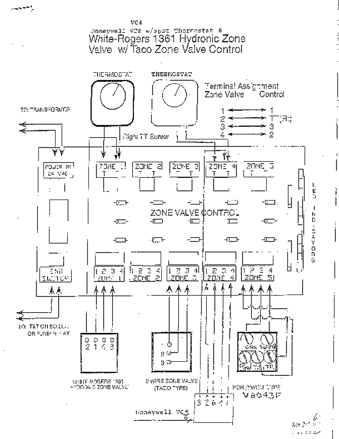
An easy-to-understand diagram that illustrates the internal component configuration. Model Data Table The table is located on the same page as the Model Layout Drawing. This table thoroughly defines each model, as well as all necessary ordering information. These tables may vary slightly between sections to best describe each product line.Wiring Diagram – Read and Draw Wiring DiagramsMultiple Unit Installations – Flagship Marine
