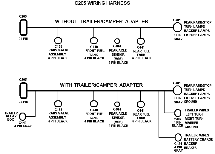
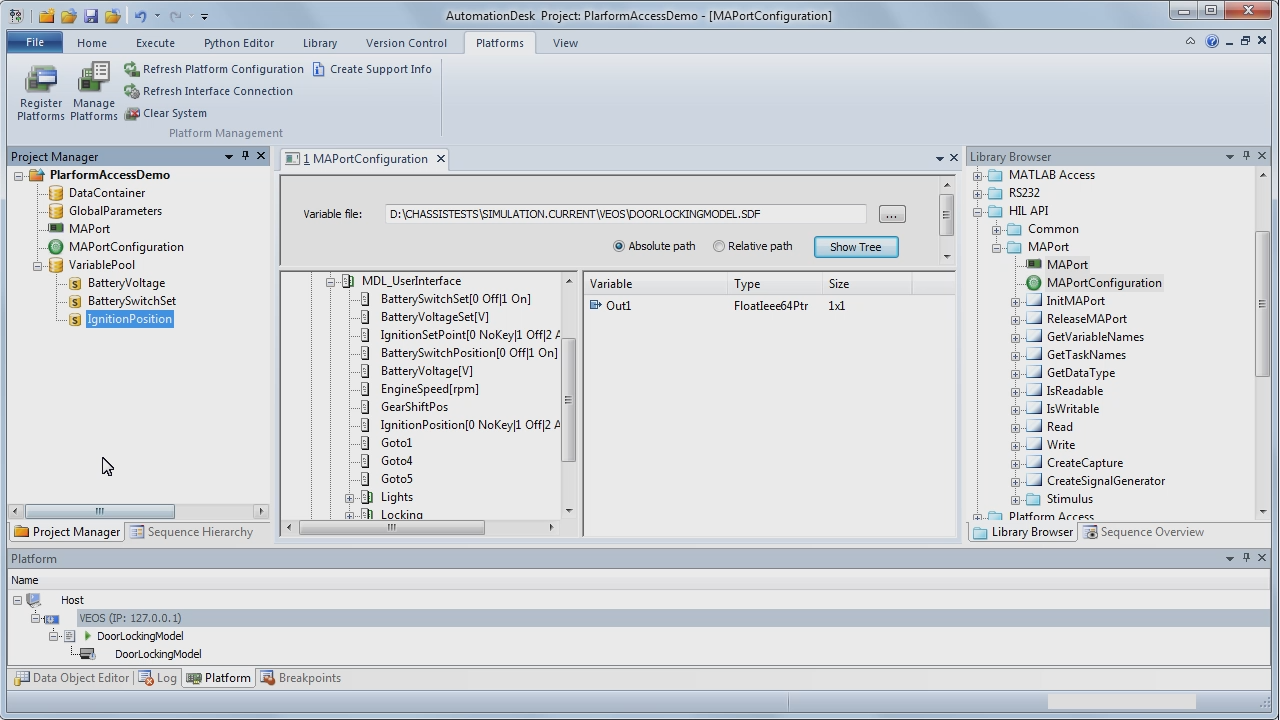
Discussion Post your Vector wiring diagrams here! Eagle Tree Systems.

Here are some of the diagrams from the manual for reference. Figure Gateway and testing devices connection schematic.

.. dSPACE MicroAutoBox II (DS1): It is the main ECU of t .. Vector CANoe is a universal development, test and analysis environment for CAN bus systems.
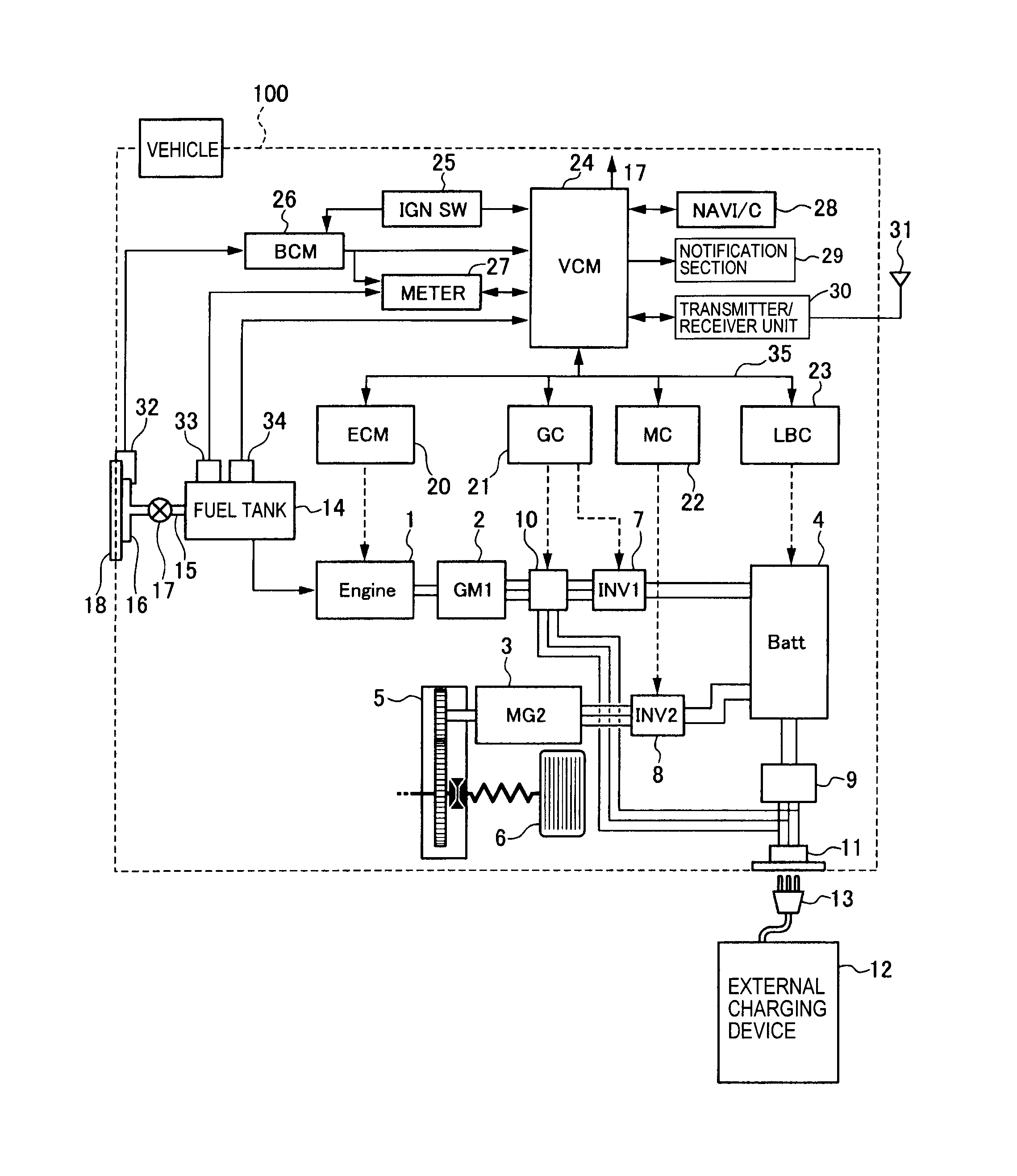
Keywords: dSpace MicroAutoBox II, ECCOM gearbox, CVT, continuously variable CANalyzer, droop limit, ZF Friedrichshafen AG, driveline, powertrain, VDC,. ECU, TCU, vehicle .. Efficiency chart of the ECCOM ..

on the Xerion and a CAN message table used in the connection setup Vector CANalyzer. GmbH, Robert Bosch GmbH, Vector Informatik GmbH,.
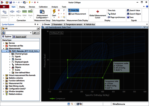
XI-Works Tula chose dSPACE’s rapid prototyping tool MicroAutoBox II. To validate the Maintenance Information), wiring diagrams, part locators, repair videos etc.
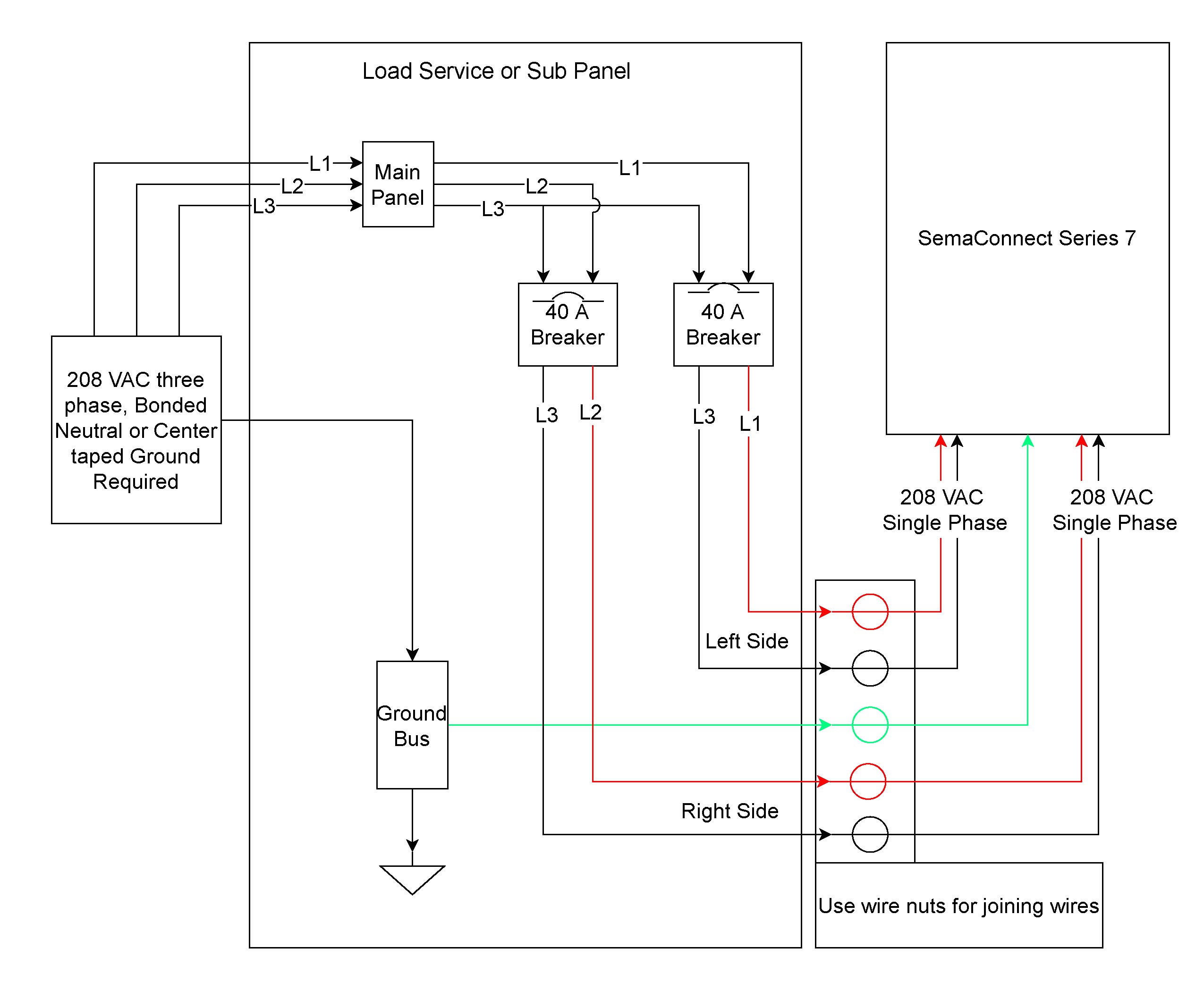
CANalyzer is the universal software analysis tool for ECU networks and. Product Information Table of Contents 1 Introduction to CANoe Bus Systems and of the tests (e.g. CAPL/C# files, test tables, test diagrams or parameter files).
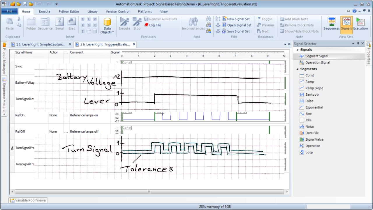
.. hardware > Easy bus connection via Vector Scope Bus Probe > Oscilloscope .. Setting up a Local Interconnect Network (LIN) using dspace MicroAutoBox.The best value around, Vector Z25 is engineered and assembled by master craftsmen, packing a ton of muscle into our 13″ tall NX chassis.
This desktop is also immensely reliable, designed to outlast even the toughest challenges, making it a perfect home office, family, or dorm room PC to last all four years! Just as with every Velocity Micro.
MC7 – Store messages into CANalyzer (Vector) file format. This Script stores CAN messages in a file format which is compatible to the CANanlyzer file format used by Vector. This ASCII file format is also used by other simulation software vendors.
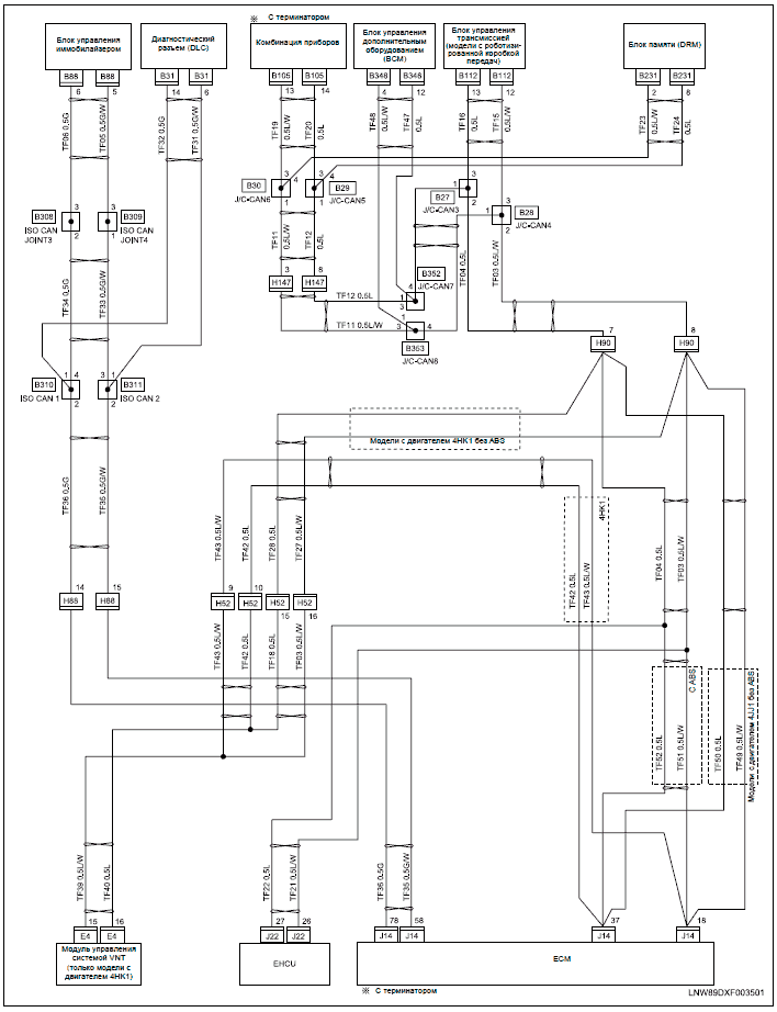
Those tools . The TLC3-FCR-2 is a stand-alone electronic fan coil controller with one control loop.
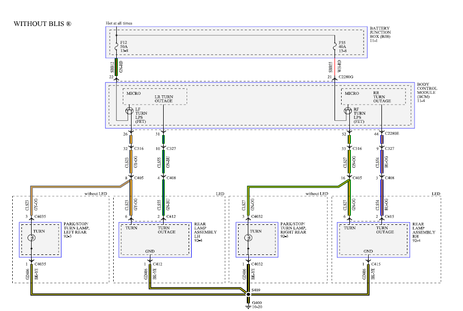
The TLC3-FCR-2 features 1 NTC. Aug 02, · On the other side of the PSU are two outputs: one is another xt60 connector (indicated in red in the image below) and the other is for the wiring harness that goes into the Vector.

On page 14 in the manual, it shows a diagram indicating that the second xt60 plug should go to my ESCs. USER GUIDE 1 MicroVector Multirotor/Fixed Wing Flight Controller + OSD User Guide March, Version Software Version +.CANoe.
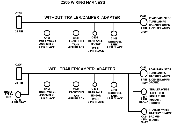
Product Information – PDFMC7 – CANalyzer (Vector) file format – Avisaro AG