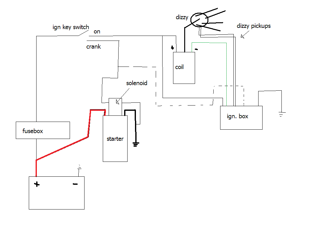
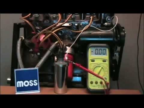
A quick and easy way to diagnose ballast resistor failure is to bypass it by running a temporary jumper wire from the battery to the coil. If it starts. Ok any ideas?

Back of the ignition switch. Are we looking at a burnt wire?
Or a fusible link? Stumbles from time to time.
Mostly now that it is. from Sierra Vista AZ.
here’s from a chilton manual None of the factory Duraspark systems I had had a ballast resistor. Is it from an 8 cyl.
. I’m working on a Ford with a red Duraspark I ignition setup.
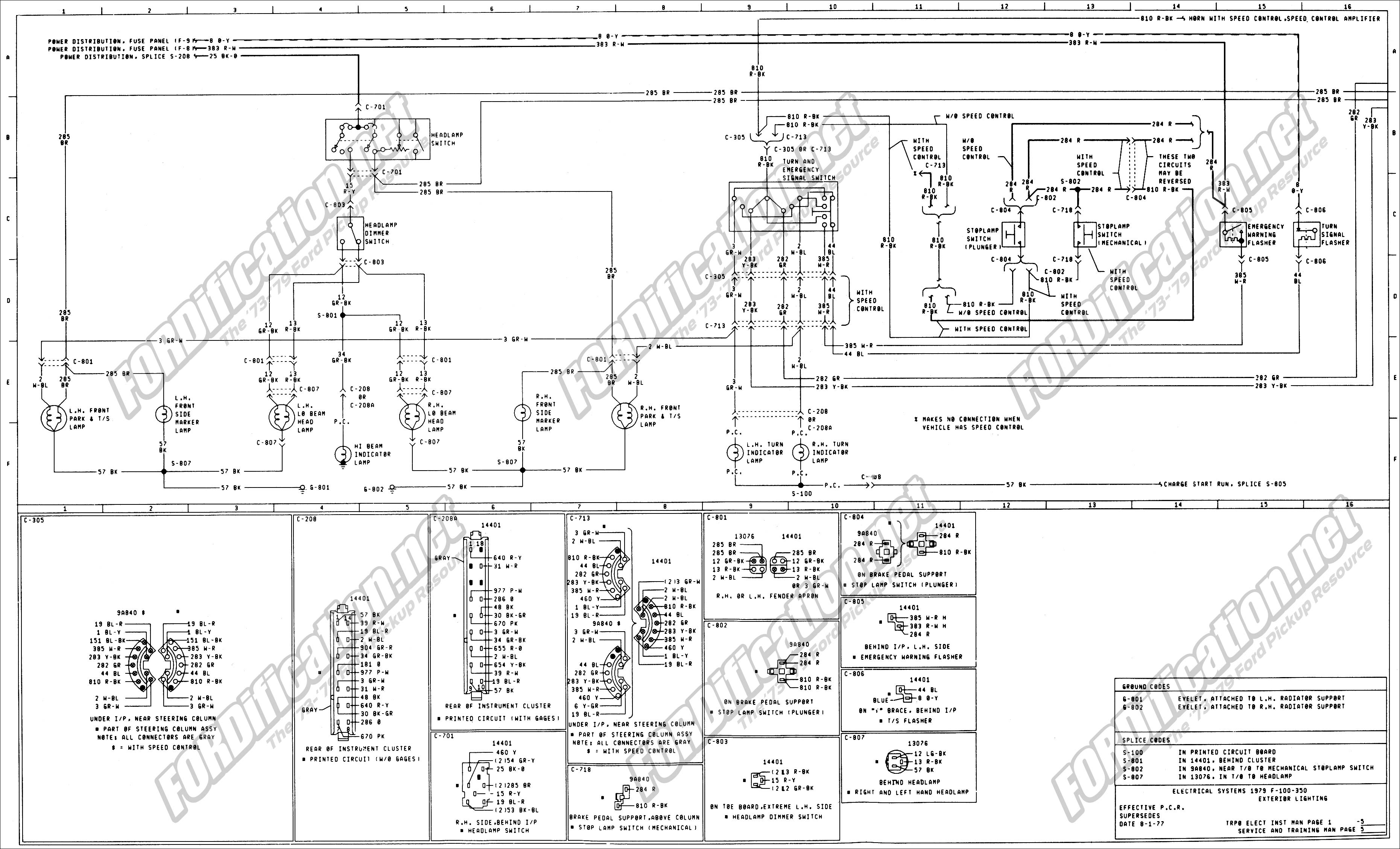
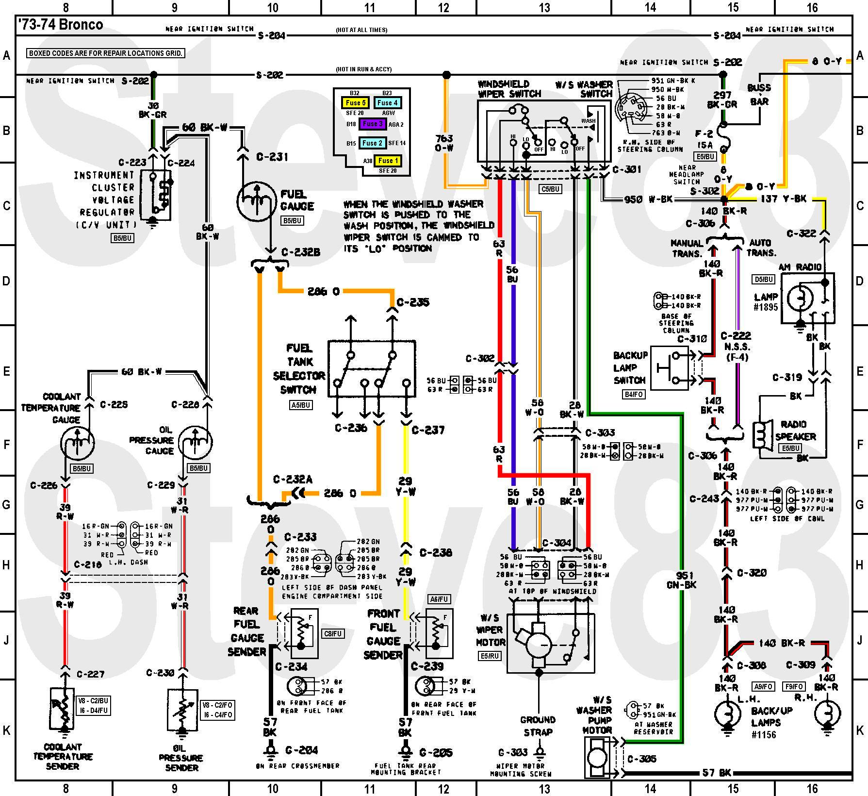
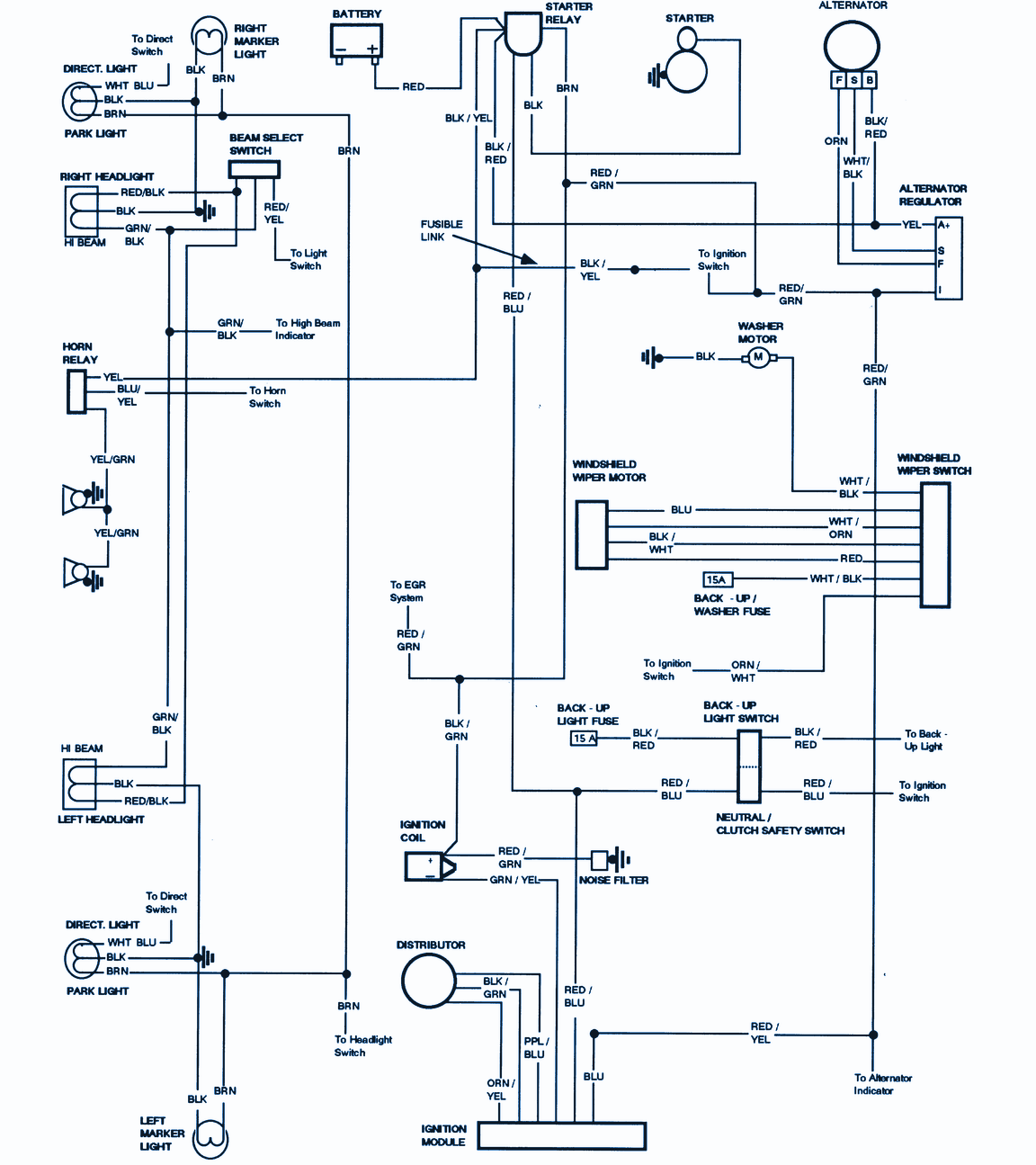
The car was. Ford Truck Wiring Diagrams (Bronco, Econoline, F Series) ..
• Heavy dashed lines indicate an ignition switch accessory =A VARIABLE RESISTANCE .. MARKER LAMP FEED (NON TRACTOR) TO AUX.
CIRC. BREAKER. That is why we have assembled the MSD Ignition Wiring Diagrams and Tech Notes.
Book. This book ..
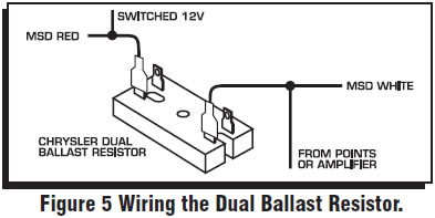
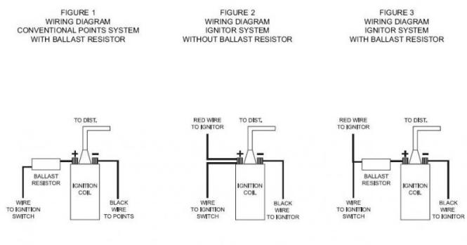
A ballast resistor is not necessary with any MSD Series Ignition but can be left in-line if originally equipped. .
FORD (Before ). Dodge Ballast Resistor Wiring – Chrysler ballast resistor wiring diagram moreover full mopar electrical diagram also p ca77 in addition chrysler alternator wiring diagram also fan belt diagram d dodge moreover dodge aspen wiring diagram electrical system circuit as well as subaru forester front suspension. Some History and Facts.
Some History. This type system was used on to Ford V-8 passenger car and light truck engines.
This refers to the Duraspark II control module with a BLUE strain relief bushing, one 4-pin connector, and one 2-pin connector. The ballast resistor get’s installed on the wire from the ignition switch to the positive side of the ignition coil and it’s the wire that is hot when the key is on run not start.
the start coil wire should still have 12 volts. One second and I’ll pull up the wiring diagram.
Ford Ignition Wiring Diagram – wiring diagram plymouth reliant moreover wiring diagram motorhome chevy p30 moreover gm tilt steering column wiring diagram further gm firing orders in cadillac firing order diagram moreover honda wiring diagram also fiat spider wiring diagram as well as mustang no wires on my coil so which ones do i need together with. Need a Ford Truck Wiring diagram.
Submitted: 9 years ago. Category: Classic Car. horrible wiring, possibly bad ballast resistor, have a f with a c.
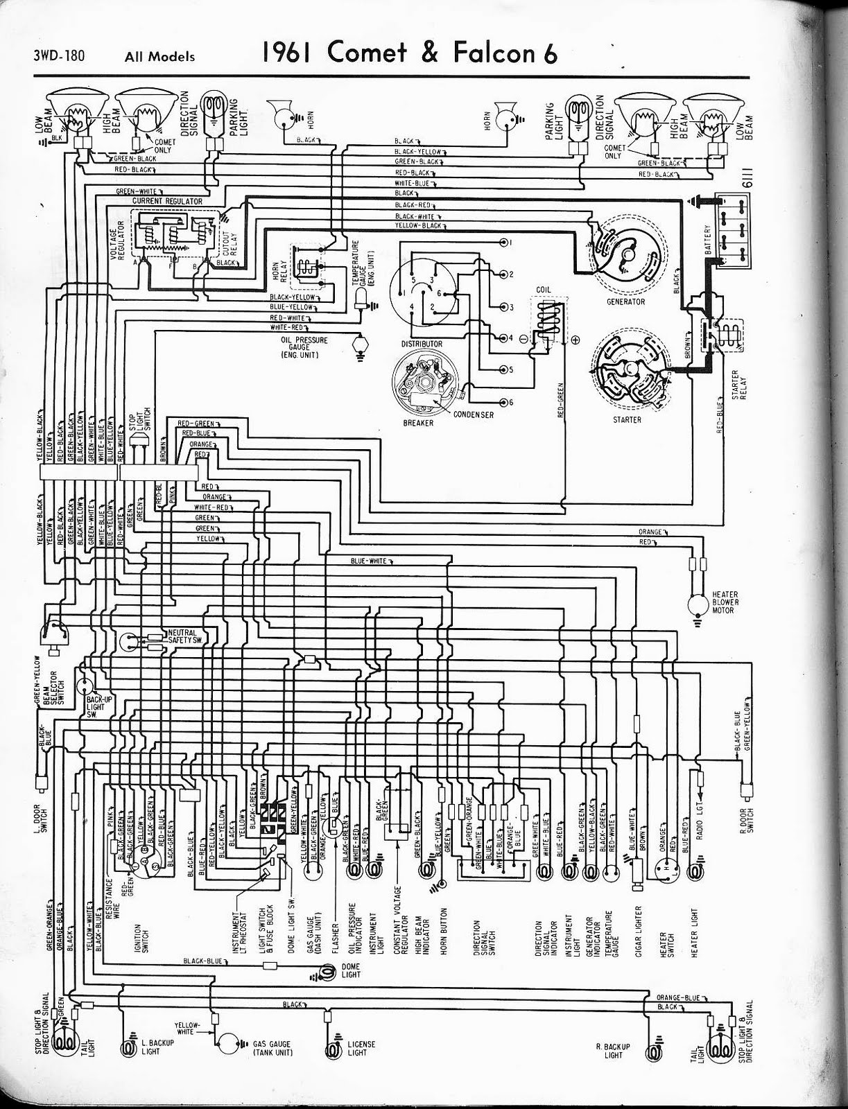
2 of the voltage regulator wires came unpluged. one has 12volts when the ignition is turned off the other has no voltage.F ignition troubles Please help!!!
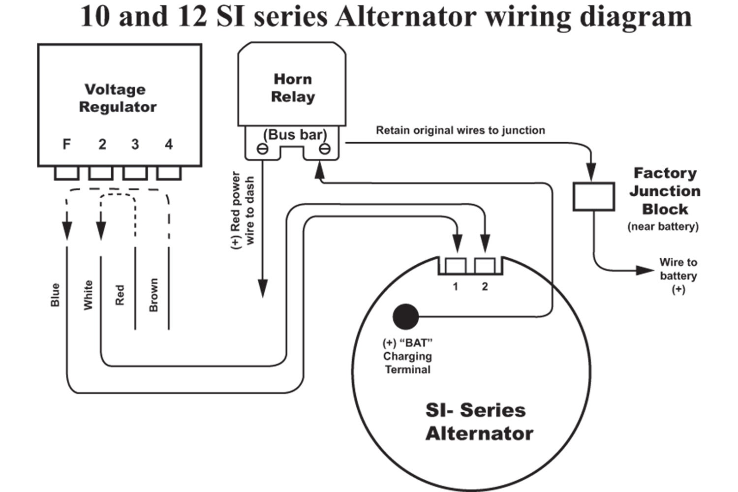
– schematron.org : 4×4 and Off-Road ForumFord Ignition Wiring Diagram – Car Repair Manuals And Wiring Diagrams