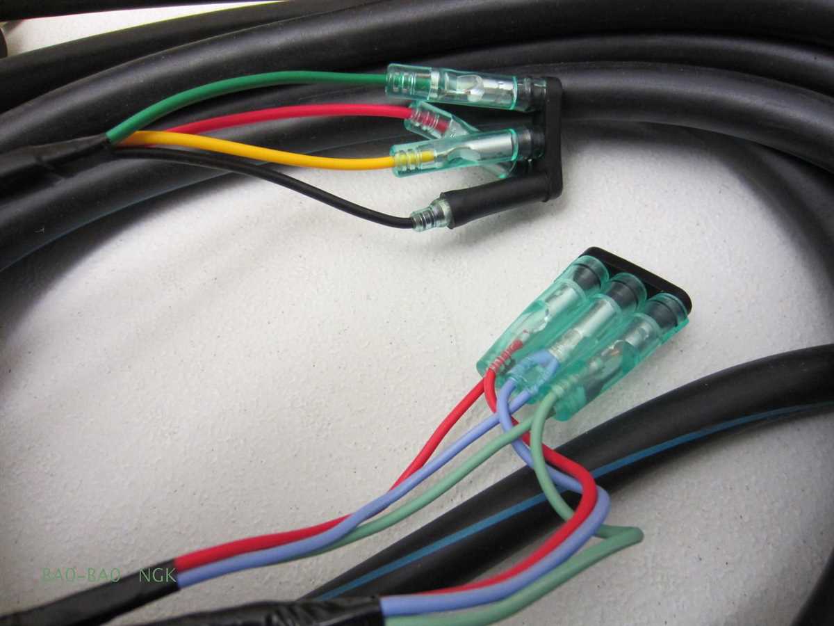
The remote control wiring diagram is an essential tool for anyone looking to install or repair a Yamaha outboard’s remote control system. Yamaha outboard motors are known for their durability and reliability, and having a properly functioning remote control system is crucial for seamless operation.
The remote control wiring diagram provides a detailed overview of how different components, such as the throttle, shift, and ignition switches, are connected and how they interact with each other. It helps troubleshoot any issues that may arise with the remote control system and ensures that all connections are correct and secure.
Understanding the Yamaha outboard remote control wiring diagram is important for both boat owners and mechanics. It allows boat owners to have a better understanding of their boat’s electrical system and enables them to make small repairs or adjustments on their own. Mechanics can also use the wiring diagram as a reference when diagnosing and repairing any electrical issues with the remote control system.
Overall, the Yamaha outboard remote control wiring diagram is a valuable resource for anyone working with Yamaha outboard motors. It ensures proper installation and functioning of the remote control system, and helps troubleshoot any issues that may arise. By using the wiring diagram, boat owners and mechanics can ensure the smooth operation and longevity of their Yamaha outboard motor.
Understanding the Yamaha Outboard Remote Control Wiring Diagram
When it comes to operating a Yamaha outboard motor, having a clear understanding of the wiring diagram for the remote control is essential. The remote control is an important component that allows the operator to control various functions of the outboard motor, including starting and stopping the engine, adjusting the throttle, and shifting gears. By understanding the wiring diagram, operators can troubleshoot any issues that may arise and ensure proper functioning of the remote control.
The Yamaha outboard remote control wiring diagram provides a visual representation of the electrical connections between the various components of the remote control system. It includes detailed information about the wires, connectors, and switches used in the system, as well as their respective functions and locations. This diagram serves as a roadmap for understanding how the remote control system is wired and how it interacts with the outboard motor.
Key components:
- Throttle and shift cables: These cables connect the remote control to the throttle and gear shift mechanisms on the outboard motor. They allow the operator to adjust the speed and direction of the motor.
- Start/stop switch: This switch is used to turn the engine on and off. It is typically a momentary switch that is held down to start the engine and released to stop it.
- Key switch: The key switch is used to activate the electrical system of the outboard motor. It is similar to the ignition switch in a car and must be turned to the “on” position for the engine to start.
- Ignition switch: The ignition switch is used to power the electrical components of the motor, such as the spark plugs and fuel pump. It is typically a toggle or rocker switch that can be turned on and off.
- Control box: The control box houses the various switches and controls of the remote control system. It is typically mounted on the boat’s console or dashboard for easy access by the operator.
In conclusion, understanding the Yamaha outboard remote control wiring diagram is essential for proper operation and troubleshooting of the remote control system. By familiarizing themselves with the key components and their functions, operators can ensure a smooth and efficient boating experience.
What is a Yamaha Outboard Remote Control?
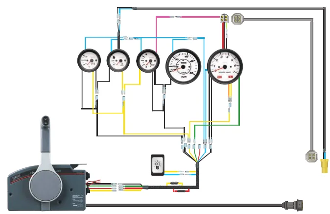
A Yamaha Outboard Remote Control is a device used to remotely control the operation of a Yamaha outboard motor. It allows the boat operator to control various functions of the outboard motor without having to manually reach for the engine controls.
The remote control is connected to the outboard motor through a wiring harness, which allows for the transmission of signals between the control unit and the motor. This wiring diagram shows the various connections and components involved in the operation of the remote control system.
The remote control typically includes an ignition switch, throttle control, trim control, and various other buttons and switches for controlling different functions of the outboard motor. It is usually mounted on the boat’s console or a nearby control panel for easy access.
With a Yamaha Outboard Remote Control, the boat operator can start and stop the motor, adjust the speed and direction of the boat, and control the tilt and trim of the outboard motor. This provides convenience and ease of operation, particularly for larger boats where the engine controls may be located further away from the operator’s position.
In summary, a Yamaha Outboard Remote Control is a vital component for controlling the operation of a Yamaha outboard motor from a convenient and accessible location on the boat. It allows for the remote operation of various functions of the motor, providing ease of use and convenience for the boat operator.
Components of a Yamaha Outboard Remote Control
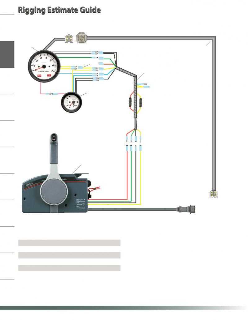
The Yamaha outboard remote control is a vital component in the operation of a Yamaha outboard motor. It allows the operator to control various functions of the motor from a distance, providing convenience and ease of use. The remote control is designed to be mounted on the boat’s console or steering wheel, allowing for easy access and operation.
The remote control consists of several key components that work together to control the outboard motor. These components include:
- Control Handle: The control handle is the main interface between the operator and the outboard motor. It includes various buttons, switches, and levers that allow the operator to control the throttle, shift gears, and engage other functions such as the trim and tilt.
- Control Cables: The control cables are responsible for transmitting the operator’s input from the control handle to the outboard motor. They are connected to the control handle on one end and to the motor on the other, allowing for precise control of the motor’s functions.
- Control Box: The control box houses the electrical components of the remote control system. It contains circuit boards, connectors, and wiring that connect the control handle and control cables to the outboard motor. The control box is typically located near the console or steering wheel of the boat.
- Electrical Connections: The remote control system includes various electrical connections, such as wiring harnesses and connectors, that link the control handle, control cables, and control box together. These connections ensure the proper transmission of signals and power between the components.
Overall, the Yamaha outboard remote control is a sophisticated system that allows for precise control of a Yamaha outboard motor. It enhances the boating experience by providing ease of operation and convenience for the operator.
Importance of the Wiring Diagram
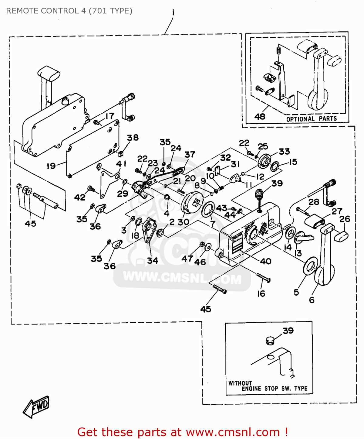
When it comes to Yamaha outboard remote control wiring, having access to a comprehensive wiring diagram is crucial. The wiring diagram provides a visual representation of the electrical connections and wiring components of the remote control system, allowing technicians and boat owners to understand how the system is wired and troubleshoot any issues that may arise.
A wiring diagram helps to ensure that the remote control system is installed correctly and that all connections are made properly. It provides a clear map of where each wire should be connected, preventing mistakes or incorrect wiring that could lead to electrical problems or malfunctions. Without a wiring diagram, it can be challenging to navigate the various wires and connections, increasing the risk of errors.
The wiring diagram also serves as a reference guide for maintenance and repairs. When a problem occurs with the remote control system, the diagram can help identify the specific component or connection that may be causing the issue. By following the diagram, technicians can quickly locate the problem area and make the necessary repairs or replacements.
Furthermore, the wiring diagram allows for easier upgrades or modifications to the remote control system. When adding new components or making changes to the wiring setup, having a diagram ensures that everything is connected correctly and reduces the likelihood of damaging any electrical components. It provides a roadmap for the installation process, making it more straightforward and efficient.
In summary, the wiring diagram is an essential tool for Yamaha outboard remote control installations, repairs, and modifications. It ensures that the system is wired correctly, aids in troubleshooting, and provides a reference guide for maintenance and upgrades. Investing in a high-quality wiring diagram can save time, prevent errors, and help maintain the reliability and functionality of the remote control system.
How to Read the Yamaha Outboard Remote Control Wiring Diagram
If you own a Yamaha outboard motor and need to understand the wiring diagram for the remote control, it’s important to know how to read it. The wiring diagram provides a visual representation of the electrical connections and components in the remote control system. By understanding this diagram, you can troubleshoot any issues and make necessary repairs or modifications.
Identify the Key Components
The first step in reading the Yamaha outboard remote control wiring diagram is to identify the key components. These may include the ignition switch, throttle position sensor, trim switch, key switch, and other control functions. Each component is represented by a symbol or label in the diagram, making it easier to understand the overall layout.
Follow the Circuit Flow
Next, follow the circuit flow in the wiring diagram. This means tracing the path of the electrical current from the power source to the various components and back. The diagram will typically show arrows or lines indicating the direction of the current flow. This will help you understand how the different components are connected and how they interact with each other.
Check for Connectors and Wires
Pay attention to the connectors and wires in the wiring diagram. These are represented by symbols such as dots, lines, or arrows. The diagram will show where each wire or connector is located and how they are connected to the different components. Understanding the wire connections is crucial for troubleshooting and making sure everything is properly connected.
Refer to Color Codes and Symbols
Color codes and symbols are often used in the Yamaha outboard remote control wiring diagram to further clarify the connections. For example, different colors may be used to represent wires of different gauges or functions. Symbols may indicate the type of switch or the purpose of a particular connection. Make sure to refer to the key or legend provided in the diagram to understand these codes and symbols.
Consult the Owner’s Manual or Service Manual
If you’re having trouble understanding the wiring diagram, consult the owner’s manual or service manual for your Yamaha outboard motor. These manuals often include detailed explanations and diagrams specific to your model. They can provide additional information and guidance to help you read and interpret the remote control wiring diagram accurately.
Overall, understanding the Yamaha outboard remote control wiring diagram requires careful observation and interpretation. By familiarizing yourself with the key components, following the circuit flow, and referring to color codes and symbols, you can gain a clear understanding of how the remote control system is wired. This knowledge will enable you to troubleshoot and repair any electrical issues effectively.
Common Wiring Diagram Symbols and Terminology
In the world of electrical wiring diagrams, there are certain symbols and terminology that are commonly used to represent various components and connections. These symbols and terms can help to decipher the wiring diagram and understand how the various parts are connected.
One common symbol is the square with a diagonal line, which represents a switch. Switches are used to control the flow of electricity in a circuit and can be either manually operated or automatically controlled.
Another common symbol is the circle with a plus sign, which represents a power source. This can be a battery or an electrical outlet, depending on the specific application. The power source provides the electrical energy needed to power the circuit.
Other symbols that are frequently used include the zigzag line, which represents a resistor, and the parallel lines, which represent a capacitor. Resistors and capacitors are used to control the flow and storage of electrical energy in a circuit.
When reading a wiring diagram, it’s important to understand the terminology as well. For example, the term “ground” refers to a connection that provides a reference point for electrical potential. This is typically connected to the earth or a metal structure to ensure electrical safety.
Another term to be familiar with is “terminal,” which refers to a point where a component or conductor is connected to the rest of the circuit. Terminals are typically labeled with letters or numbers to indicate their function or position in the circuit.
In summary, understanding the common symbols and terminology used in wiring diagrams can help to make sense of the electrical connections and components being represented. By being familiar with these symbols and terms, it becomes easier to understand how the various parts of a circuit are connected and how they function together.
Troubleshooting Tips for Yamaha Outboard Remote Control Wiring
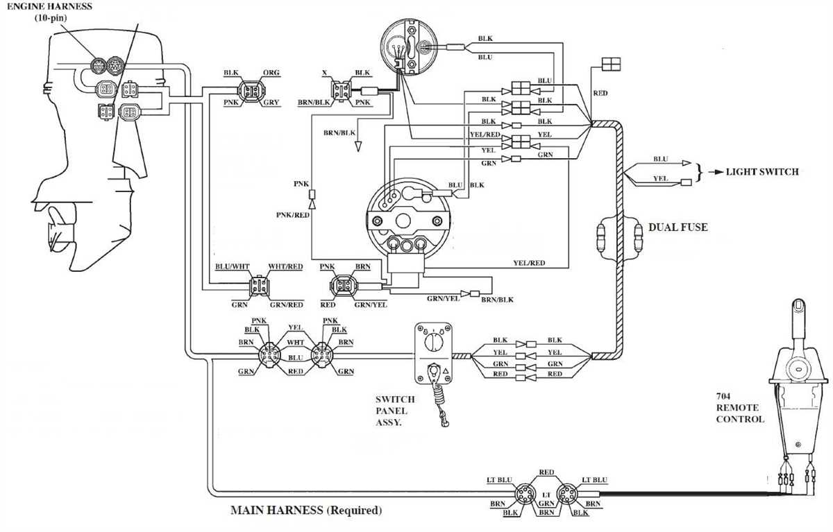
If you are experiencing issues with your Yamaha outboard remote control wiring, there are a few troubleshooting steps you can take to identify and resolve the problem. Here are some tips to help you troubleshoot common wiring issues.
1. Check for Loose or Damaged Connections
- Inspect all connections, including the wiring harness, connectors, and terminals, for signs of damage or corrosion.
- Tighten any loose connections and replace any damaged components.
2. Test the Voltage
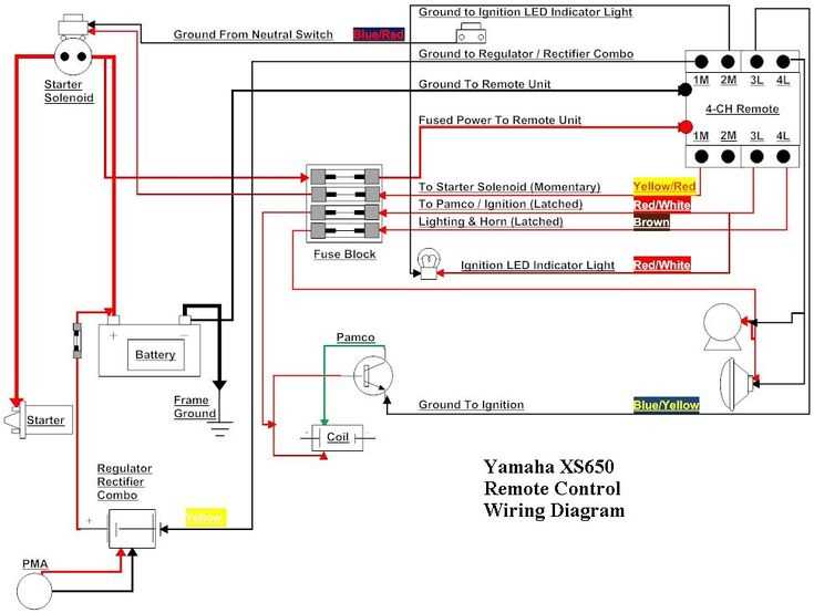
- Using a multimeter, test the voltage at various points along the wiring to ensure that power is reaching the appropriate components.
- If there is no voltage or lower than expected voltage, there may be a break in the wiring or a faulty component.
3. Verify Proper Grounding
- Check that the grounding connections are secure and free of corrosion.
- Make sure that the ground wire is properly connected to the battery or engine block.
4. Inspect the Control Unit
- Examine the control unit for any visible damage or signs of water intrusion.
- If the control unit appears to be damaged, it may need to be replaced.
5. Consult the Wiring Diagram
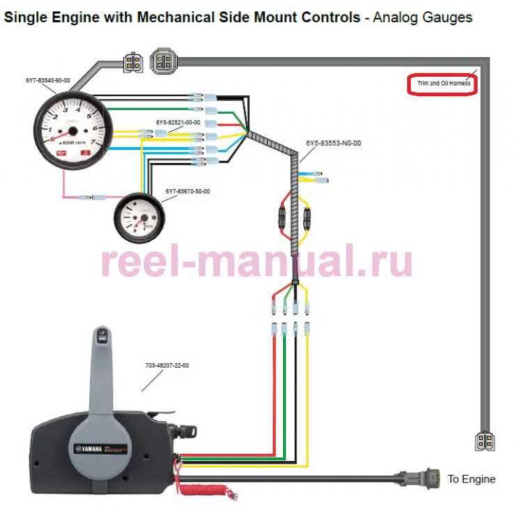
- Refer to the Yamaha outboard remote control wiring diagram to ensure that all connections are properly configured.
- Compare your wiring setup to the diagram to identify any discrepancies or incorrect connections.
By following these troubleshooting tips, you can effectively diagnose and resolve issues with your Yamaha outboard remote control wiring. Remember to always refer to the manufacturer’s documentation and seek professional assistance if needed. Proper wiring is essential for the safe and efficient operation of your outboard motor.