This has a mini XLR socket.

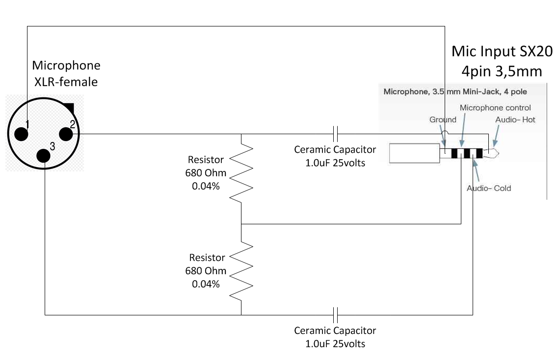
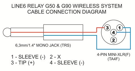
microphone cable wireless conversion xlr Page 23 of the following document contains the circuit diagram for the PT40 Pin 1 is connected to ground via an inductor and signal path is via pin 2. for that transmitter, and the wiring diagram for your headset mic in order to.
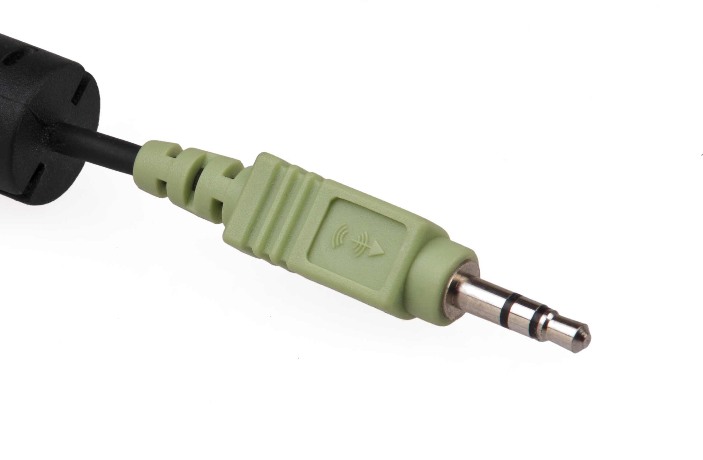
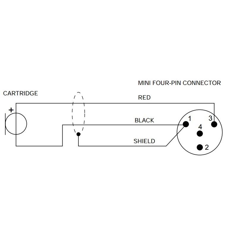
If you do not see the wiring diagrams for the wireless microphones you need, Audio-Technica Hirose Connector Electrovoice/Telex 4-Pin Mini Connector. Pin 2: Bias (+5Vdc) Pin 3: Audio Pin 4: Bias return – active bias management circuit (jumpered to pin 3 when used with most condenser microphones). This has a mini XLR socket.
microphone cable wireless conversion xlr Page 23 of the following document contains the circuit diagram for the PT40 Pin 1 is connected to ground via an inductor and signal path is via pin 2. for that transmitter, and the wiring diagram for your headset mic in order to.
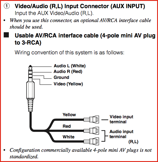
Microphone wiring and compatibility information for hundreds of wireless transmitters. Connector: mm stereo locking Code: SR .

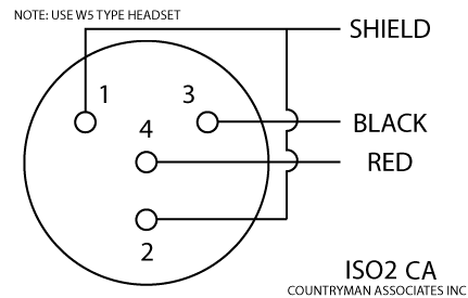
AEQ, PAW, L- , XLR (with included 1/8″ to XLR adaptor installed), XLR preamp, XLR preamp, XLR diagram, Jumper 1 to 2. Pin 1 = S Pin 3 = B Pin 4 = R Use W5 type headset.Find great deals on eBay for 4 pole mm male repair headphone jack plug. Shop with confidence.
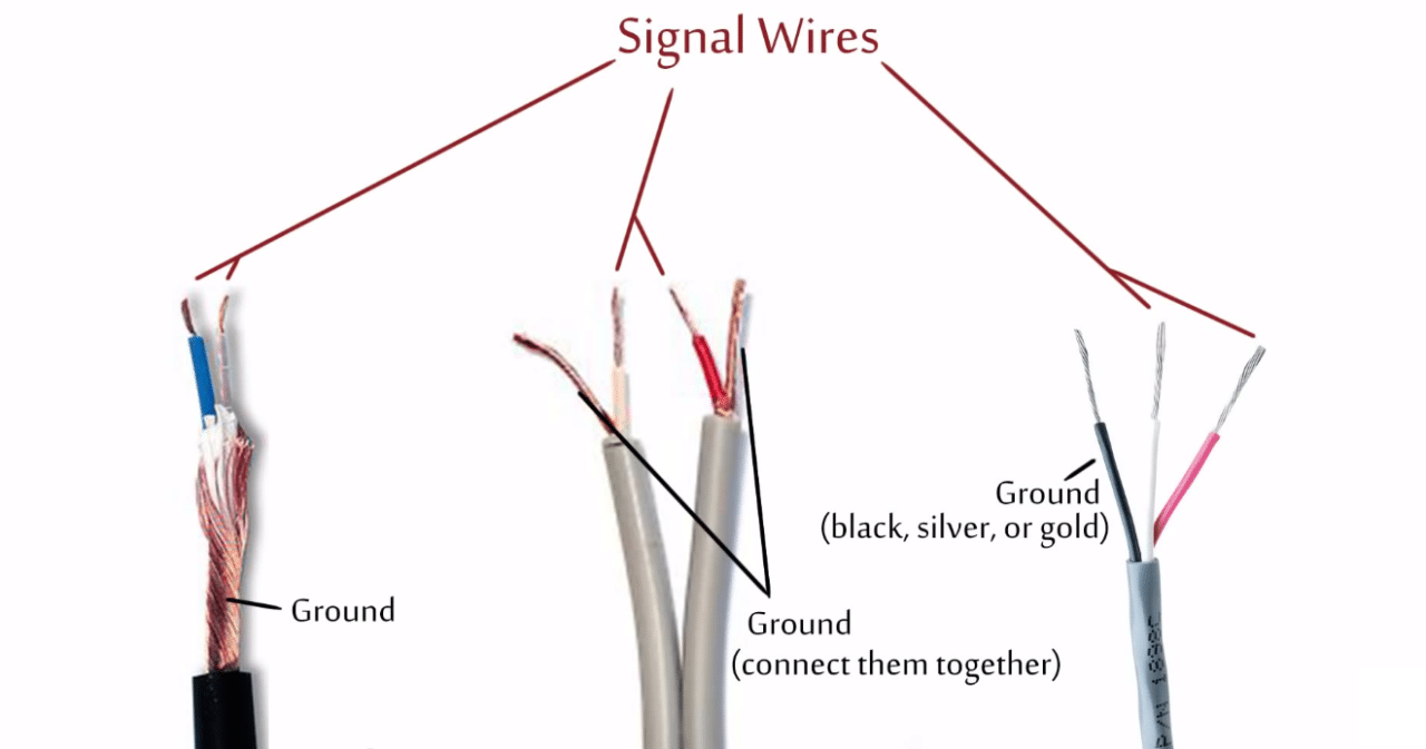
Mic and Headphones Wiring Diagram for Pc how to hack a headphone jack circuit basics how to hack a headphone jack inner copper wire is the microphone signal how to connect two wired mic red and white into audio jack 3 5 microphone jack wiring diagram further vintage telephone wiring diagram further puter microphone also 3 5 mm audio input.
4-Pole Headphone Jack Replacement: Replace a damaged 4-Pole headphone jack (found in headphones with an in-line microphone) by removing it and soldering on a new connector.
Connect a microphone with a standard XLR connector to your computer with this XLR to mini USB adapter. XLR jack at one end, Mini USB port on the other.
Supports USB full-speed. Our Team is .

Headphone wire color coding. Ask Question.
All 3 are coated in a lacquer you need to burn or scrape off before you solder. With standard headphone plugs, with the plug facing away from you, the right pin is right, the center pin is ground, and the left pin is left.
Need .Microphone and Wireless Transmitter Wiring | schematron.orgMini XLR Adapter: Pro Audio Equipment | eBay