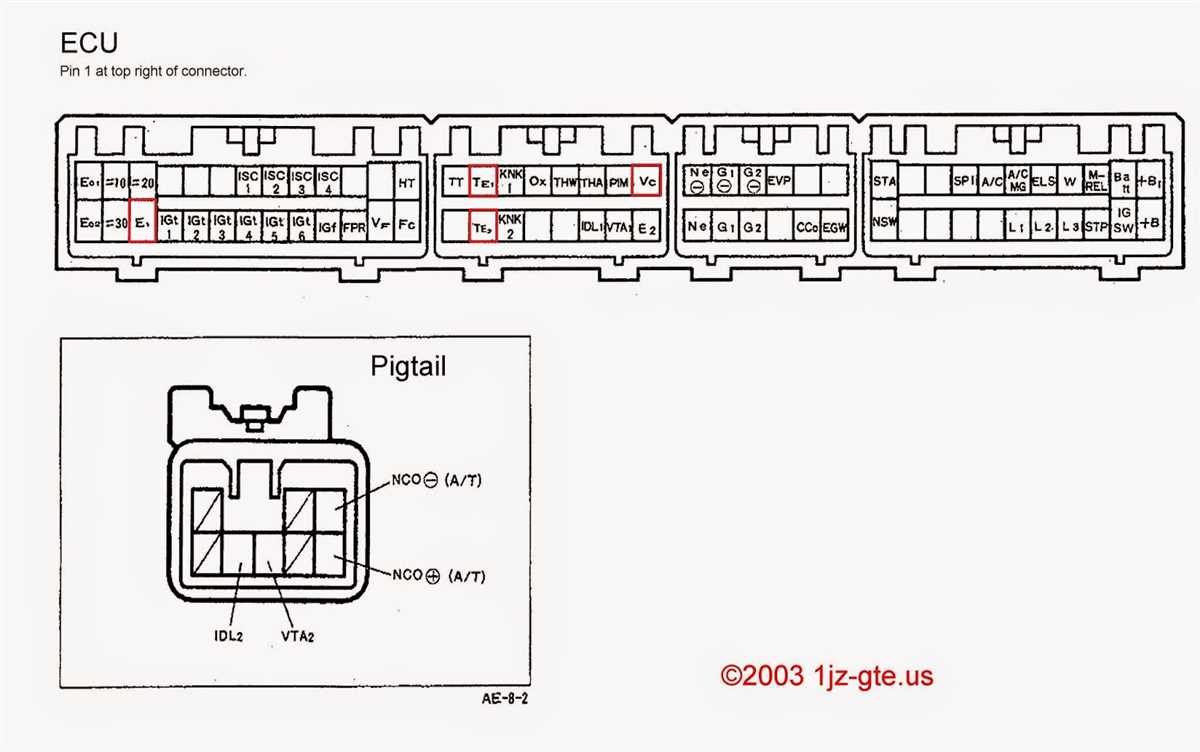
The ECU Master is a powerful engine management system that allows precise control over various aspects of engine performance. It is widely used in the aftermarket tuning industry to achieve optimal power and efficiency. To ensure proper installation and functionality, it is essential to have a thorough understanding of the ECU Master wiring diagram.
The wiring diagram serves as a visual representation of the electrical connections between various components of the engine management system. It outlines the connections between the ECU Master unit, sensors, actuators, and other peripheral devices. Understanding this diagram is crucial for troubleshooting any issues that may arise during the installation or operation of the ECU Master.
The ECU Master wiring diagram typically includes information about the power supply connections, ground connections, sensor inputs, and output signals. It also provides details on the pin assignments for various connectors, allowing for easy identification and connection of the necessary wires. Following the wiring diagram ensures that the correct voltages and signals are sent to the appropriate components, preventing any potential damage or malfunction.
Ecu Master Wiring Diagram
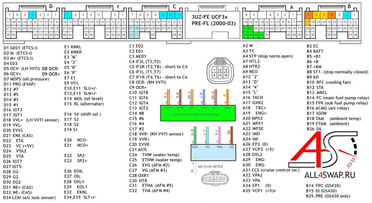
The Ecu Master wiring diagram is a detailed schematic that outlines the connections and wiring configuration of an Ecu Master device. It is used as a reference guide for technicians and enthusiasts who are installing or troubleshooting an Ecu Master system.
The Ecu Master wiring diagram typically includes information on the various components of the system, such as the ECU (Engine Control Unit), sensors, actuators, and other related devices. It shows how these components are interconnected and what signals are transmitted between them.
One of the key features of the Ecu Master wiring diagram is its ability to provide a clear visual representation of the wiring connections. This makes it easier for technicians to identify the correct wire color codes, pinouts, and connector types, ensuring accurate and secure connections.
The Ecu Master wiring diagram also includes valuable information on power supply connections, ground points, and any additional wiring modifications that may be required for specific installations or configurations. This helps ensure that the Ecu Master system operates reliably and minimizes the risk of electrical issues.
In summary, the Ecu Master wiring diagram is an essential tool for anyone working with an Ecu Master system. It provides a comprehensive overview of the system’s wiring configuration, helping technicians and enthusiasts accurately install, diagnose, and troubleshoot the Ecu Master system.
What is an Ecu Master?
An Ecu Master, also known as an Engine Control Unit Master or ECU Master, is an advanced electronic device used in automotive engineering to control the various functions of an engine. This sophisticated system acts as the brain of the vehicle by receiving inputs from sensors, processing data, and sending appropriate signals to other components to ensure optimal performance and efficiency.
ECU Masters are typically used in high-performance vehicles or racing cars where precise control over engine parameters is crucial. They can be programmed to monitor and adjust parameters such as ignition timing, fuel injection, turbo boost pressure, and transmission shifting points. With the ability to store and execute complex algorithms, ECU Masters enable engineers to fine-tune engine performance and achieve desired outputs.
The wiring diagram of an Ecu Master provides a visual representation of how the various components of the system are connected and interact with each other. It showcases the wiring routes, connections, and pin configurations of sensors, actuators, and other devices, helping technicians and engineers understand the electrical layout and troubleshoot any issues that may arise.
Importance of a Wiring Diagram
When it comes to working with electrical systems, having a clear and accurate wiring diagram is of utmost importance. A wiring diagram is a visual representation of the electrical connections and components in a system, and it provides essential information for troubleshooting, installation, and maintenance.
A wiring diagram allows technicians and electricians to understand how the different components and wires are connected, ensuring that everything is properly installed and connected. It helps identify potential issues or errors in the wiring, preventing accidents, malfunctions, or damage to the system.
With a wiring diagram, individuals can trace the path of electricity and verify that it flows correctly through the system. This is particularly crucial when working with complex systems or when making modifications or upgrades to an existing electrical setup. It helps ensure that the right wires are connected to the right components, and that all connections are secure and functioning properly.
A wiring diagram is also an invaluable tool for troubleshooting. If there is an issue with the electrical system, having a diagram allows technicians to quickly locate the problem and identify the possible causes. It saves time and reduces the risk of errors, enabling efficient repairs and minimizing downtime.
In conclusion, a wiring diagram is an essential document for anyone working with electrical systems. It provides a comprehensive overview of the connections and components, ensuring that everything is installed correctly and functions properly. Whether it is for installation, maintenance, or troubleshooting, having a clear and accurate wiring diagram is vital for the safety and efficiency of the electrical system.
Components of an Ecu Master Wiring Diagram
An Ecu Master wiring diagram is a visual representation of the electrical connections and components in an engine control unit (ECU) system. It provides a detailed overview of how various components are connected and how signals flow through the system.
The diagram typically includes the following key components:
- ECU: The central component of the system, the ECU receives input signals from various sensors and controls the engine functions based on these inputs. The ECU is typically depicted as a rectangular box in the diagram.
- Sensors: These are the devices that measure different parameters such as engine speed, air temperature, throttle position, etc. Sensors are represented as small icons with specific symbols that indicate their function.
- Actuators: Actuators are the components that convert electrical signals from the ECU into mechanical actions. These can include fuel injectors, ignition coils, idle control valves, etc. Actuators are usually depicted with specific symbols that represent their respective functions.
- Wiring Harness: The wiring harness is a collection of wires that connect the various components to the ECU. It provides the necessary electrical connections for data and power transmission. The wiring harness is shown as lines of varying thickness in the diagram, with each line representing a specific connection.
- Connectors: Connectors are the physical interface points between the wiring harness and the components. They allow for easy connection and disconnection of components during installation and troubleshooting. Connectors are usually depicted as small circles or squares with numbers or letters indicating their specific function.
- Fuses and Relays: These components protect the system from electrical faults and control the flow of power to various components. Fuses are represented with specific symbols that indicate their rating, while relays are depicted as boxes with arrows to indicate their switching function.
Overall, an Ecu Master wiring diagram provides a comprehensive visual representation of the electrical connections and components in an ECU system. It is an essential tool for understanding the system’s functionality and diagnosing any electrical issues that may arise.
Step-by-Step Guide to Reading an Ecu Master Wiring Diagram
Understanding an ECU Master wiring diagram is essential for troubleshooting electrical issues in your vehicle’s ECU system. It provides a detailed overview of how the different components are connected and helps identify potential faults or areas of concern. Here is a step-by-step guide to reading an ECU Master wiring diagram.
1. Familiarize Yourself with the Symbols and Abbreviations Used
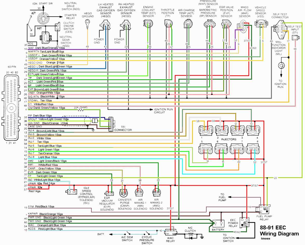
The first step is to familiarize yourself with the symbols and abbreviations used in the wiring diagram. These symbols represent different electrical components, such as sensors, switches, relays, and connectors. Additionally, there may be abbreviations used to indicate wire colors, wire sizes, or specific functions.
For example, a square box with a diagonal line represents a relay, while a circle with a wavy line indicates a sensor. Take some time to study the legend or key provided with the wiring diagram to understand the meaning of each symbol and abbreviation.
2. Identify the Power Source and Ground Connections
The next step is to identify the power source and ground connections in the wiring diagram. This will help you understand how the electrical circuit is powered and how the components are grounded. Look for symbols or labels that indicate battery power, ignition power, or ground connections.
Typically, the power source will be shown as a plus sign (+), and the ground connections will be represented by a minus sign (-) or as the symbol for Earth (a triangle with a horizontal line).
3. Trace the Wire Paths and Connections
Once you have identified the power source and ground connections, start tracing the wire paths and connections in the diagram. Begin with the power source and follow the lines to each component, noting any connections or junctions along the way.
Pay close attention to how the wires are routed and connected. Look for symbols that indicate splices, connectors, or plugs. These can be crucial areas to check if there is a malfunction or short circuit.
4. Understand the Function of Each Component
As you trace the wire paths, make sure to understand the function of each component. Refer to the legend or key to identify the purpose of individual sensors, switches, or relays. This will help you determine their role in the overall ECU system and troubleshoot any issues more effectively.
For example, a temperature sensor may be responsible for monitoring engine coolant temperature, while a pressure sensor may be used to measure fuel pressure. Knowing the function of each component will give you a better understanding of how the system operates.
5. Note Any Additional Information or Notes
Finally, make sure to note any additional information or notes provided in the wiring diagram. This could include specific instructions, recommended wire sizes, or troubleshooting tips. These additional details can be valuable when diagnosing problems or making modifications to the ECU system.
By following this step-by-step guide, you can effectively read an ECU Master wiring diagram and gain a deeper understanding of your vehicle’s electrical system. This knowledge will be instrumental in troubleshooting and resolving any electrical issues you may encounter.
Common Mistakes to Avoid when Installing an Ecu Master
Installing an Ecu Master in your vehicle can greatly enhance its performance, but it is important to install it correctly to avoid any potential issues. Here are some common mistakes to avoid when installing an Ecu Master:
1. Incorrect Wiring
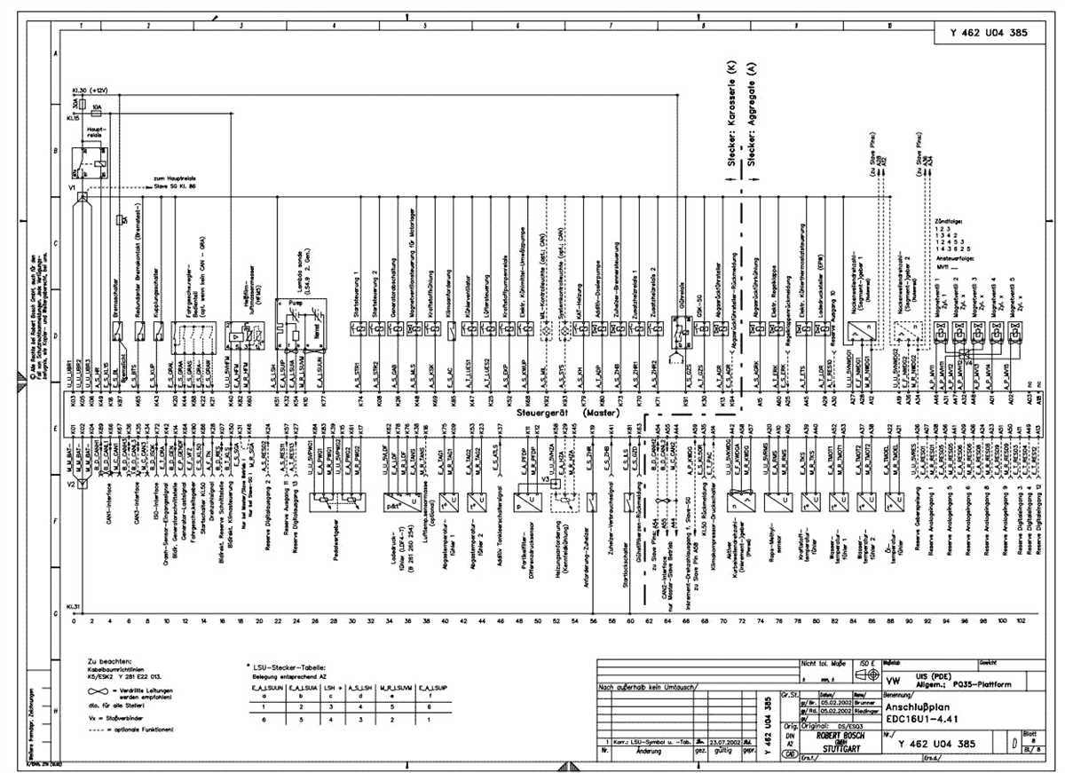
One of the biggest mistakes that people make when installing an Ecu Master is incorrect wiring. It is crucial to carefully follow the wiring diagram provided by Ecu Master and ensure that each wire is connected to the correct terminal. Incorrect wiring can lead to various issues, including electrical problems and engine malfunctions.
2. Improper Grounding
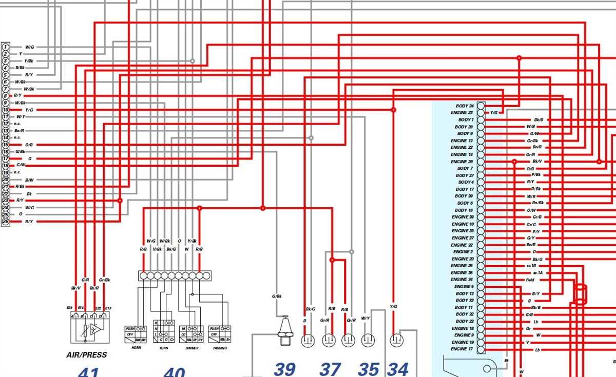
Proper grounding is essential for the Ecu Master to function correctly. Many installation errors occur due to improper grounding, such as using an inadequate ground point or not ensuring a solid connection. It is crucial to locate a proper grounding point and ensure that it is clean and securely attached to the vehicle’s chassis.
3. Failure to Calibrate Sensors
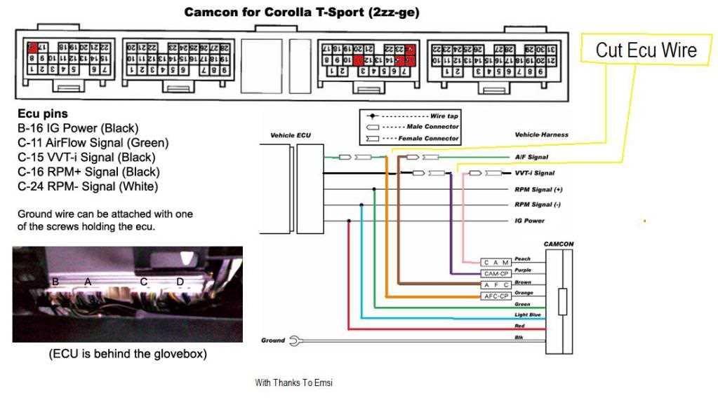
Another common mistake is failing to calibrate the sensors connected to the Ecu Master. Each sensor, such as the oxygen sensor or the MAP sensor, needs to be calibrated properly to provide accurate readings to the Ecu Master. Failing to calibrate these sensors can result in incorrect data being sent to the ECU, leading to poor engine performance.
4. Overlooking Firmware Updates
Ecu Master regularly releases firmware updates to improve functionality and fix potential bugs. Failing to update the firmware can lead to compatibility issues with other vehicle components or missing out on important performance enhancements. It is crucial to regularly check for firmware updates and install them as recommended by Ecu Master.
5. Ignoring the Ecu Master Manual
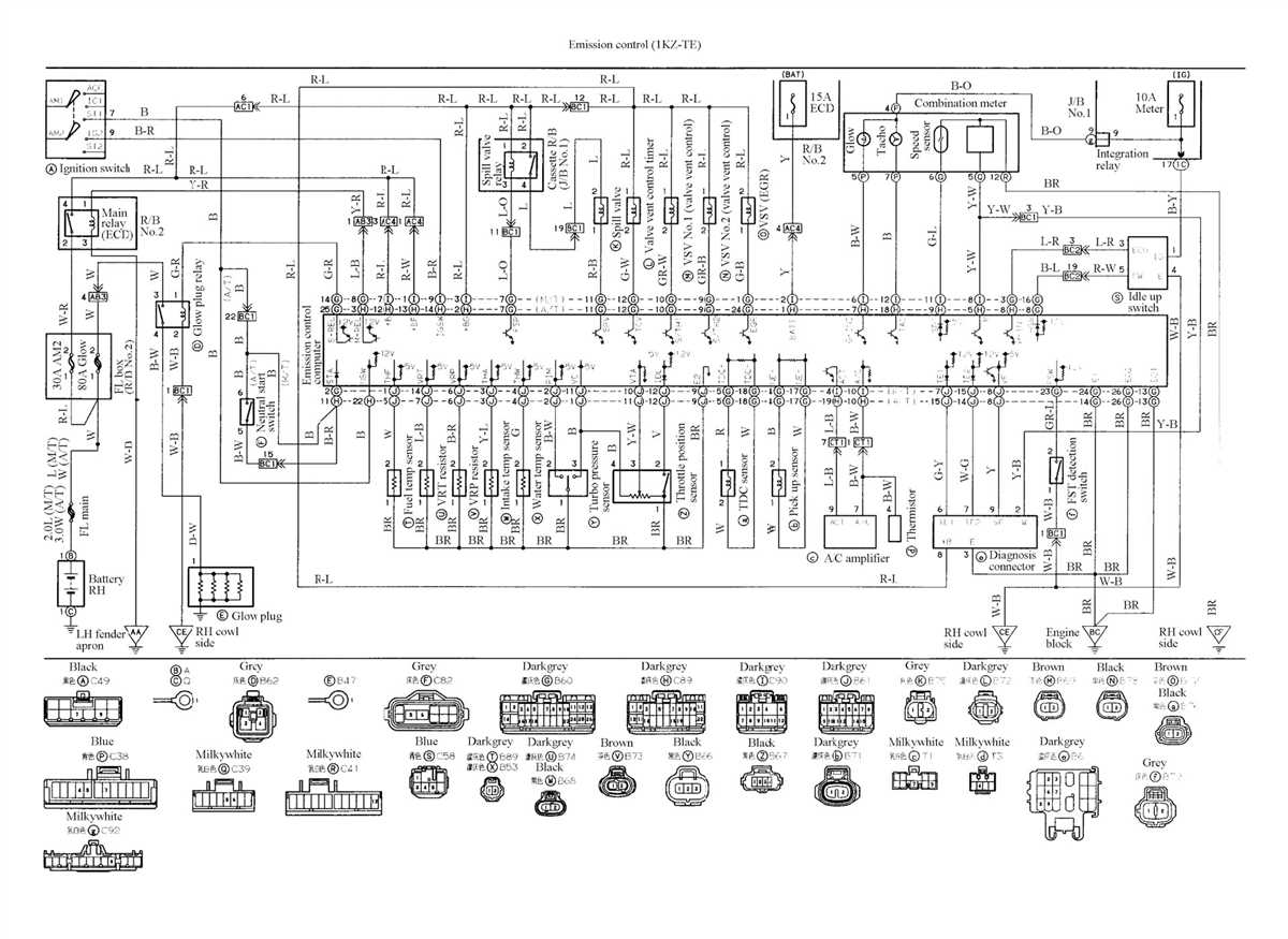
It is important to thoroughly read and understand the Ecu Master manual before installation. The manual provides important information about the product, including specific instructions for installation, wiring diagrams, and troubleshooting tips. Ignoring or neglecting the manual can lead to avoidable mistakes and difficulties during the installation process.
By avoiding these common mistakes, you can ensure a smooth and successful installation of an Ecu Master in your vehicle. Remember to carefully follow the instructions provided, double-check your wiring, and properly calibrate your sensors for optimal performance.
Troubleshooting Ecu Master Wiring Issues
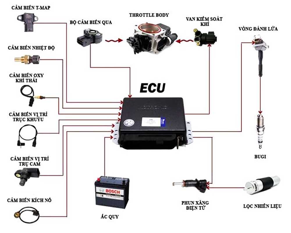
When it comes to installing and wiring an Ecu Master system, it is not uncommon to encounter issues. However, with a systematic troubleshooting approach, most problems can be easily identified and resolved. Here are some common issues and their possible solutions:
1. Check the power supply
One of the most common issues is a lack of power to the Ecu Master system. This can be caused by a blown fuse, a faulty wiring connection, or a weak battery. Start by checking the fuse and ensuring that it is properly connected and not blown. If the fuse is fine, check the battery to make sure it is fully charged and providing sufficient voltage.
2. Check the grounds
Proper grounding is essential for the Ecu Master system to function correctly. Make sure that all the grounds are securely connected and that there is no corrosion or loose connections. If necessary, clean the connections and tighten them properly.
3. Check the wiring connections
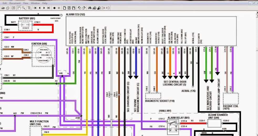
Incorrect or loose wiring connections can cause a variety of issues, including misfires, sensor malfunctions, and communication errors. Carefully inspect all the wiring connections, ensuring that they are properly connected, tight, and not damaged. Use a wiring diagram or the Ecu Master manual to verify that all the connections are in the correct places.
4. Test the sensors

If you are experiencing issues with sensor readings or inputs, it is important to test the sensors themselves. Use a multimeter or an oscilloscope to check the voltage, resistance, or signal output of each sensor. Compare the readings to the specifications provided by Ecu Master to determine if the sensors are working correctly.
5. Verify the programming
If everything else checks out, it may be necessary to verify the programming of the Ecu Master system. Ensure that the correct firmware version is installed and that the settings and parameters are properly configured for your particular setup. If needed, consult the Ecu Master documentation or reach out to their technical support for assistance.
Conclusion
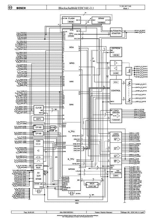
Troubleshooting Ecu Master wiring issues can be a time-consuming process, but by following a systematic approach and checking the power supply, grounds, wiring connections, sensors, and programming, most problems can be identified and resolved. If you are still unable to solve the issue, don’t hesitate to seek professional help from an experienced automotive technician or contact Ecu Master’s technical support for further assistance.