GS1 Series AC Drives User Manual – 3rd Edition – 11/09/ Basic Wiring Diagram 2–9 .
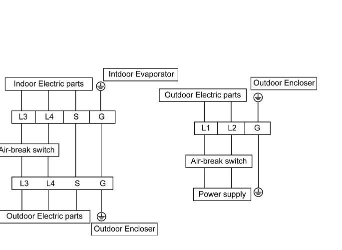
AC drives, AC power must be connected to terminals L1 and L2. single-phase, V class AC drives, the AC power can be.
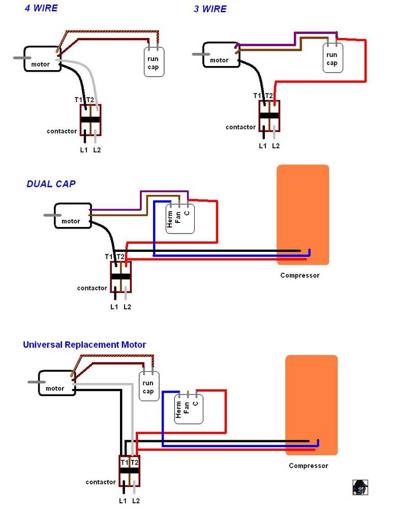
Wiring an Outdoor Condenser!: What each of the Wires is For, How it Works!
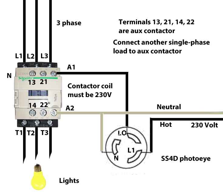
L1. L2.
T1. T2.
Compressor. Contacts. 1.
Disconnect all power before See furnace/air handler installation Split System Air Conditioner (Outdoor Section) /V. ASCT.

Anti-Short Cycle Timer (ASCT) may or may not be installed in the. L2.
L2. L2 wiring diagrams.
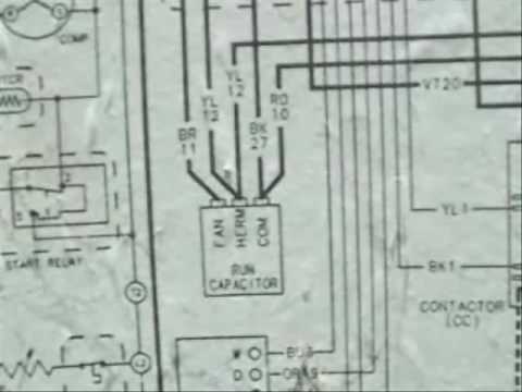
RESIDENTIAL SELF-CONTAINED. AIR CONDITIONER AND 3—MH1A (A) Heat Pump Schematic Diagram and Electric Heater Wiring Options.
v, 1 Phase, 60 Hertz. A C/B. L1.

L3. T1. T3.
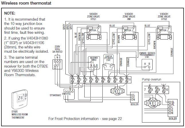
VAC between the Hot Leg L1 (Phase A, Red wire) and the Hot Leg L2 ( Phase B, . and allowances on connecting a single inverter to a code-compliant AC. Until recently I was led to believe that in refrigerator circuits both legs of AC power were feeding into the circuit but, I read that one leg, typically.it doesn’t say.
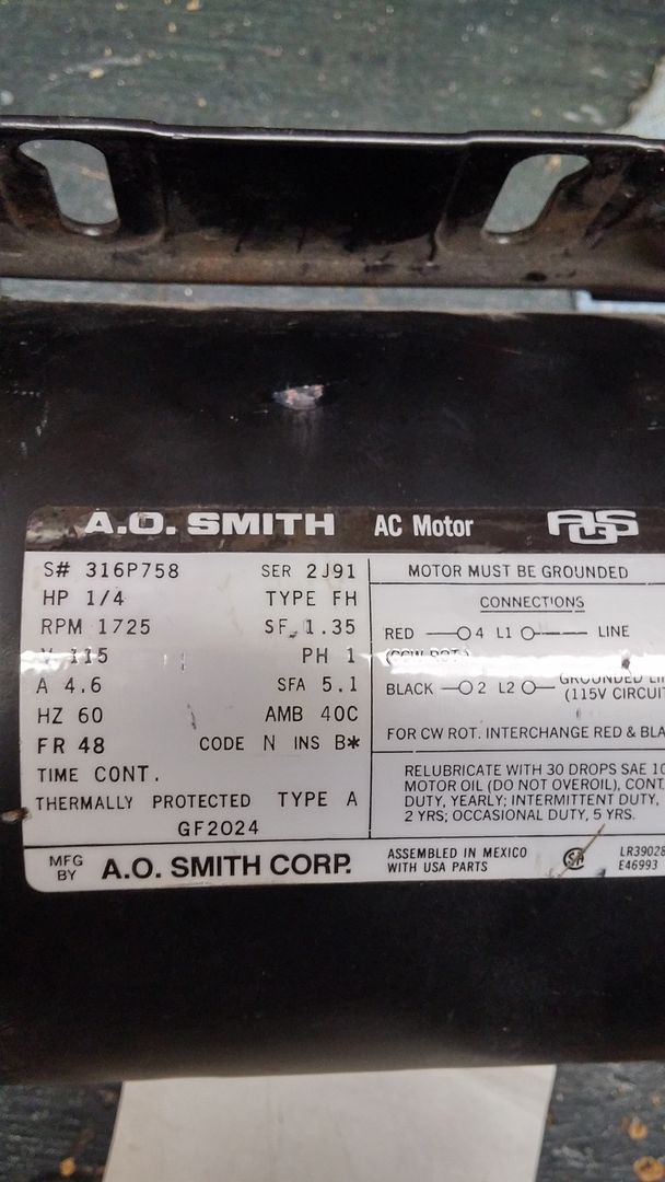
says a lot of stuff on the plate like volts. So I would connect the red wire to L1 and the black wire to L2.
HVAC Wiring Diagrams 2
But the white wire (neutral) does that go to the ground screw on the motor casing INSIDE the connection box with or without the ground connected to the same terminal. fig.
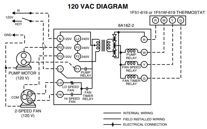
5—ma1a (a) air conditioner connection diagram with 10 kw electric heat a on off circuit breaker 60 amp on off circuit breaker see chart l2 l1 1 heater #2 2 3 4 g r y power distribution block #1 sequencer #1 compressor overload high-pressure switch compressor circuit breaker chart model 1–1/2 ton 2 ton 2–1/2 ton 3 ton size 24ANB7 Infinityt 17 Stage Air Conditioner with Puronr Refrigerant 2 to 5 Nominal Tons Wiring Diagram CONNECTION DIAGRAM SCHEMATIC DIAGRAM (LADDER FORM) TRAN V V CONT TRAN CONT COMP EQUIP COMP V V CONT / 1Ø 11 21 POWER 23 Single-phase motors are used to power everything from fans to shop tools to air conditioners. Residential power is usually in the form of to volts or to volts. Wiring a motor for volts is the same as wiring for or volts.
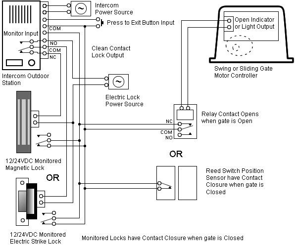
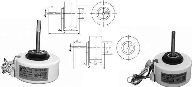
Some motors allow both volt and volt wiring by providing a combination of wires for doing so. Jun 29, · Of the 4 fan wires, tag says white to L1, then choose the fan rpm you want, connect the appropriate colour wire for that speed to L2 and cap the other 2.
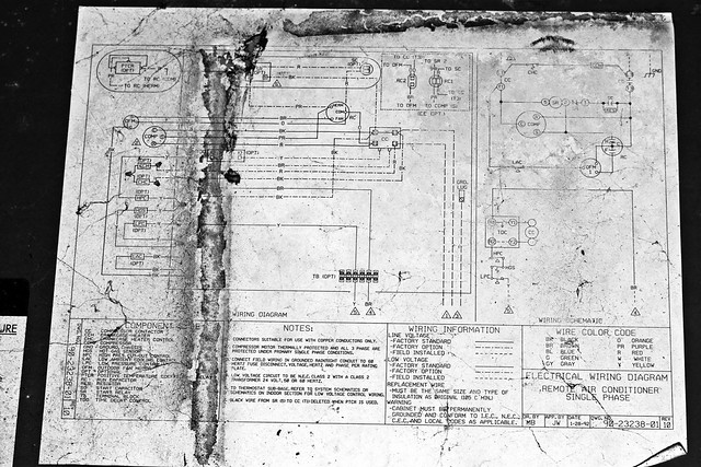
If you want raise, lower the rpm’s later, change the wire from fan that’s attached to L2.AC Motor Control Circuits | AC Electric Circuits WorksheetsElectrical Wiring Diagrams for Air Conditioning Systems – Part Two ~ Electrical Knowhow