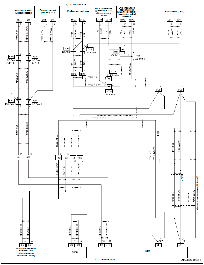
Wiring Diagrams and Trouble Diagnosis.
Duet-EA control .. sensor) or PNP switch and provides shift control or lock-up control via A/T solenoid valves.
produces a multipath, in order to test the Duet receiver. The output of the filter drives a D/A converter and is sent to the I/Q modulator. The I/Q modulator is used to.
TCM Self-diagnosis Does Not Activate (PNP,. Overdrive Park/Neutral Position ( PNP) Switch Adjustment Duet-EA control ..
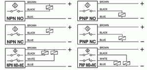
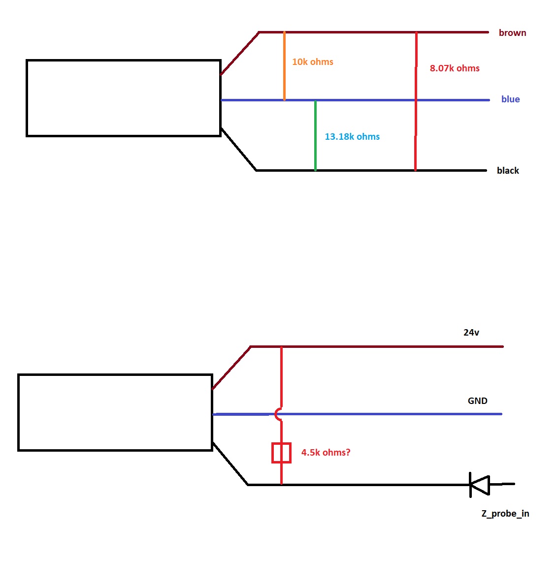
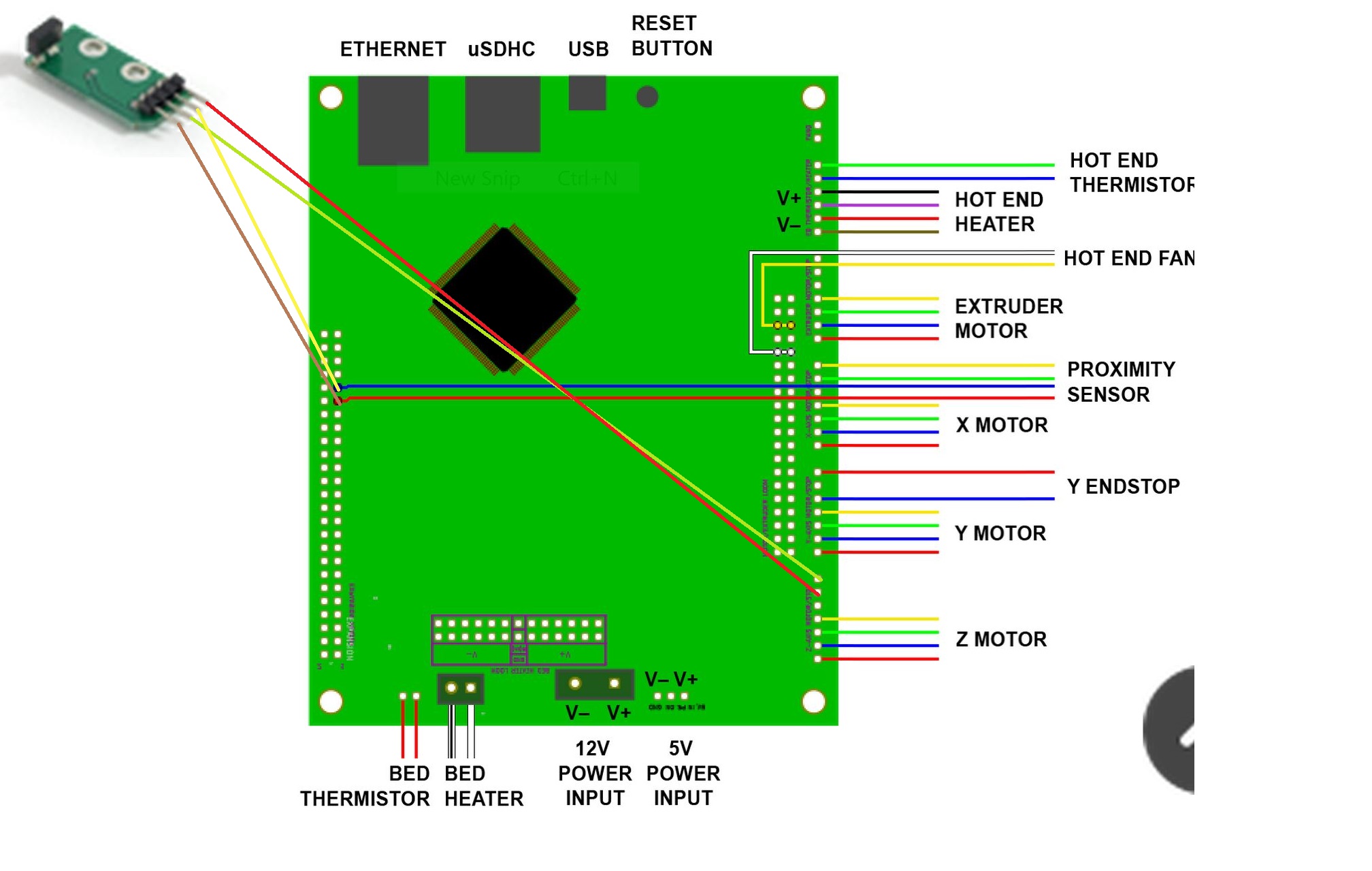
PNP switch circuit. This describes how to connect a variety of Z probes to the Duet hardware.
or capacitive sensor; PNP output normally-open inductive or capacitive sensor. Wiring Diagram — AT — PNP/SW.
Duet-EA control .. sensor) or PNP switch and provides shift control or lock-up control via A/T solenoid valves. The TCM.Duet Main wiring.
All positive fan pins are connected to Vin. The pinouts are on the back of the board (V ), a KiCAD export shows the back below for reference (this is the view from the bottom of the board, so is mirrored).
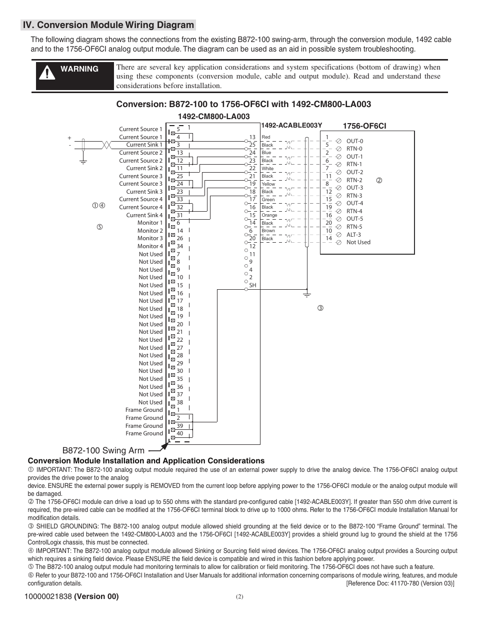
Receiver with PNP output Receiver with two analogue outputs (ANA_V, ANA_I) Output cable length mm with M12 pigtail Special Function: emitter and receiver with CX0 common wire and Teach-in emitter Receiver Receiver with two digital outputs (NPN / PNP) electric diagrams . It is therefore important to identify the type of sensor to be used with the PLC card based on the PLC manufacturer’s documentation and / or wiring diagrams. Most common in Europe is the ‘sinking’ type of input, these will be used with the PNP sensor as shown below.
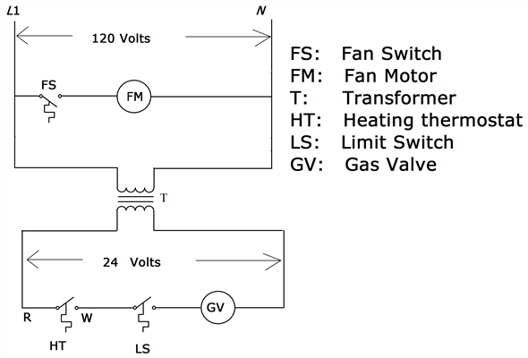
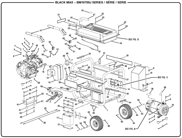
Whirlpool Duet Diagram Parts. Some parts shown may not be for your model.
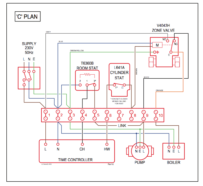
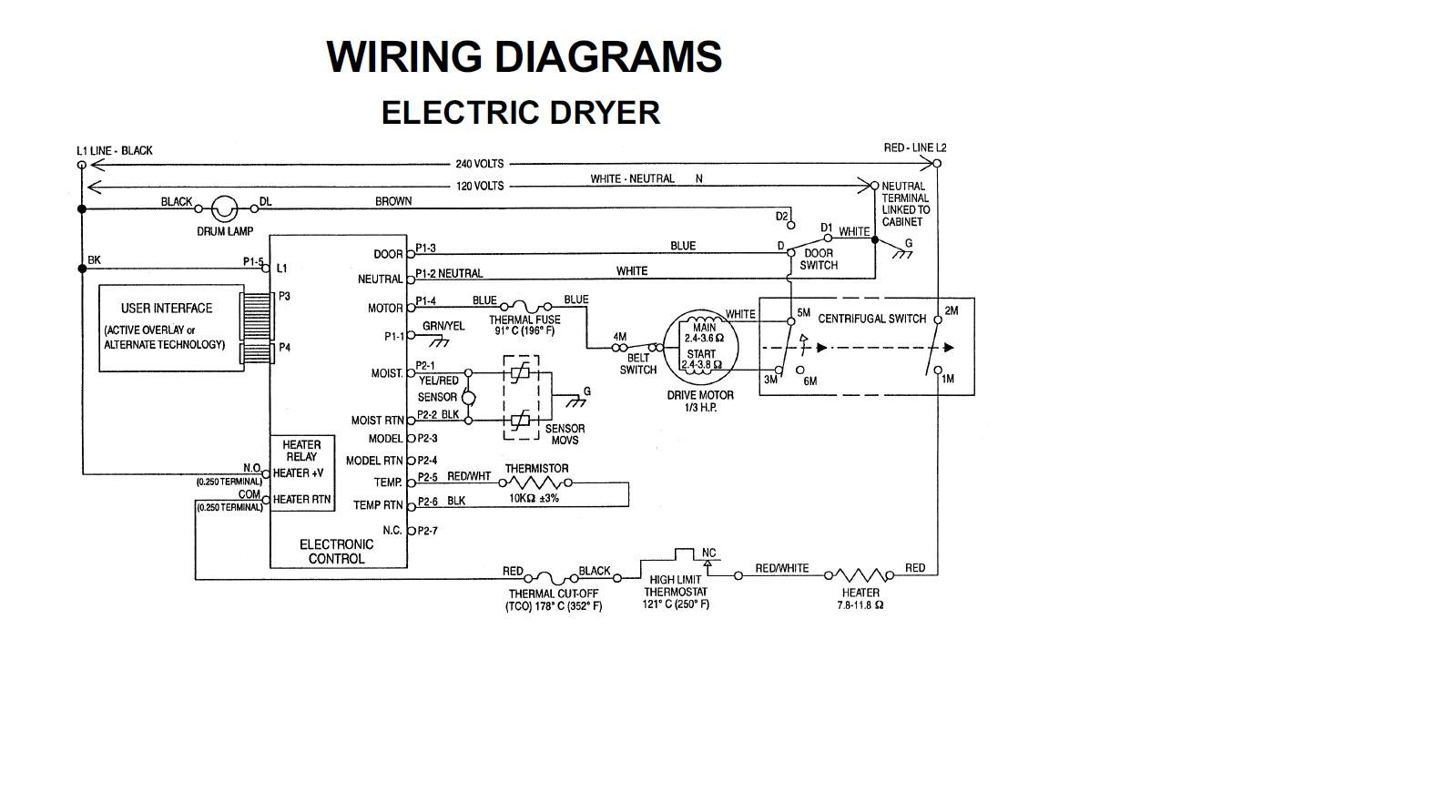
To see parts for your model only, select it from “Matching Model Numbers” on the left. Duex Wiring Diagrams.
These are the wiring diagram for v, v and of the Duex 2 and Duex 5 expansion boards for the 2nd generation Duets (Duet 2 Wifi and Duet 2 Ethernet).What is the difference between PNP and NPN when describing 3 wire connection of a sensor?Duet NPN or PNP Prox Sensor?