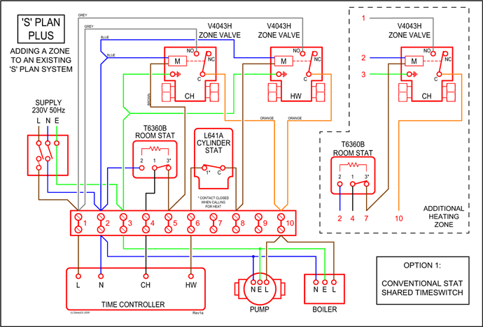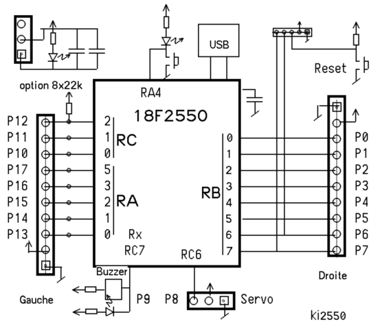
Standard Case – Wire diagram.
8. Reconnect the battery.
Reconnect Power. Continued on next page. Fine Adjustment Pot.
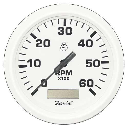
Magnetic Pick-Up Tachometer. The Faria Marine Instrument Bracket Mount Dual Engine.
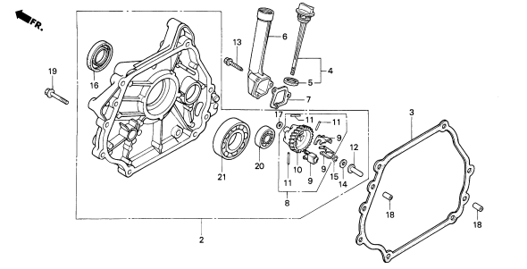
Synchronizer is designed to Like a tachometer, the Synchronizer counts “pulses” from the ignition or tach tachometer and synchronizer wiring in close proximity to these sources of. This will neither damage a Faria® tachometer nor affect accuracy when not transmitting.
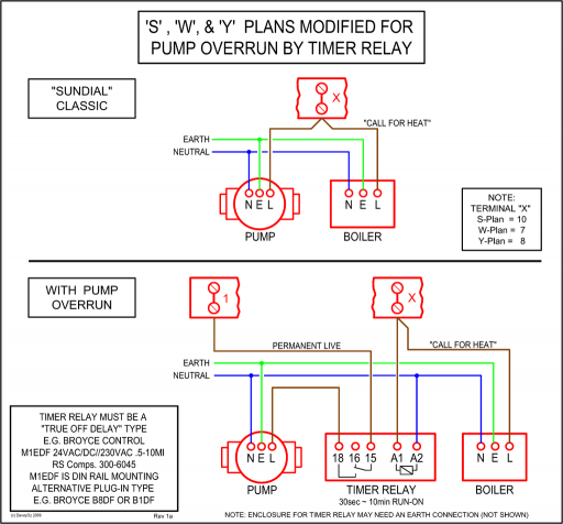
2. Be certain to use stranded, insulated wire not lighter than 18AWG that. Page of links to the technical section for Faria gauges.
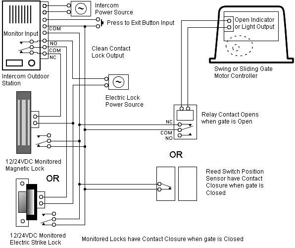
View wiring diagrams and schematics for hundreds of popular boats including Lowe, Larson. Page of links to the technical section for Faria gauges.
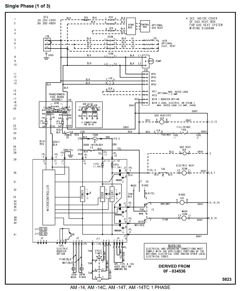
View wiring diagrams and schematics for hundreds of popular boats including Lowe, Larson.ISp – Tachometer, Outboard Applications Sheet: Faria Gauge Tester: View wiring diagrams and schematics for hundreds of popular boats including Lowe, Larson, Alumacraft, Lund, and others. Teleflex Gauges Technical Information.

Troub leshooting Guide. Adjusting the . Apr 08, · Re: Faria tach gauge wiring.
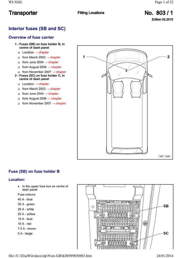
The standard side mount remote control will have a three wire plug below the ignition switch for the the three wire tachometer harness. Connect the blue lighting wire to one of the other blue lighting wires on a nearby gauge.
Faria Synchronizer greatly simplifies the task of controlling the engine throttle position to maintain synchronization. Before proceeding with the actual installation instructions, a few general comments are in order. First of all, for operation, both engines (and tachometer signal sources) must be of the same type and have the same number of.
You may not always see our instruments, but with some of the most sophisticated vehicle information and instrumentation systems in the industry, and a range of products that are rugged enough to survive on a military HMMWV (Humvee) and heavy construction equipment, or with innovative styling for your boat or RV, Faria Beede Instruments, Inc.
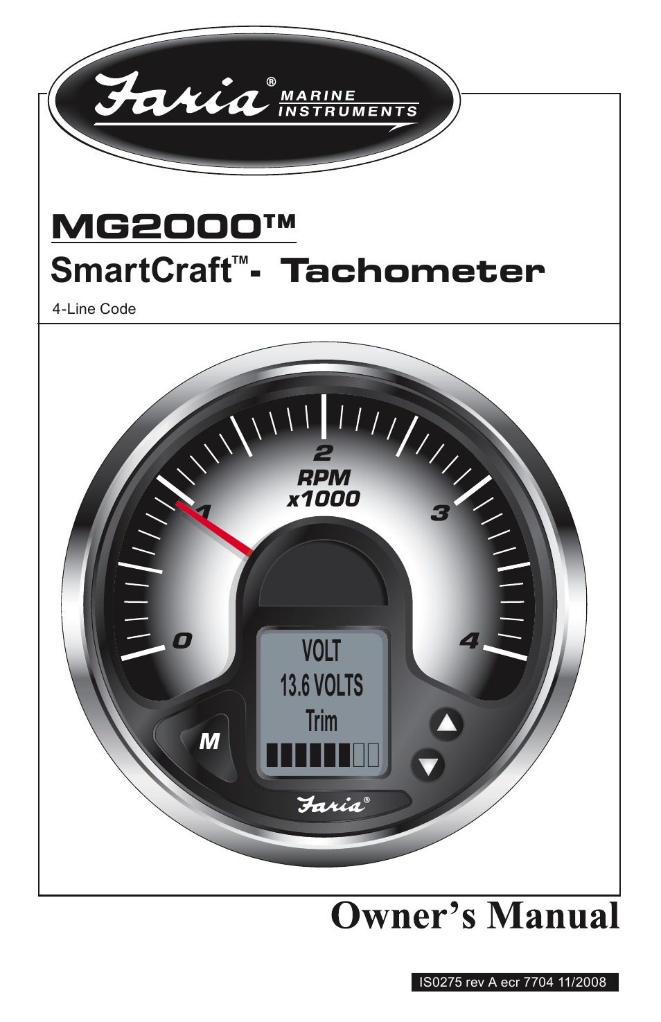
has the right products to meet future global needs. Appendix II Faria Instrument Tester Instructions (IS) Appendix III ABYC – Engine and Accessory Wiring Color Code Guide Appendix IV Choosing the Proper Sender Appendix V Outboard Tachometer Application Table (IS) Appendix VI Sending Unit Resistance Values Table (IS) Appendix VII Troubleshooting Quick Reference Guide Contents.Gauge Technical Informationfaria tachometer | eBay
