Fix your DeVilbiss Compressor today with parts, diagrams, accessories and repair DeVilbiss E3D 1 Horsepower-Single Cylinder Air Compressor Parts.
E INSERT CUSTOMER WIRING INSTRUCTIONS. Please contact HUSKY for further assistance.
VAC Air Compressor Wiring Instructions. *A circuit breaker is preferred.
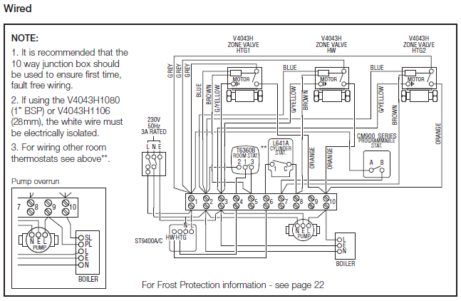
Use only a fuse or circuit breaker that is the same rating as the branch circuit the air compressor is operated on. If the air.
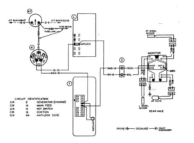
Do not connect air compressor to a V 3-phase system. A V system can proper lifting equipment for unloading and moving to installation site. Install Using a for a diagram of the compressor and its components.
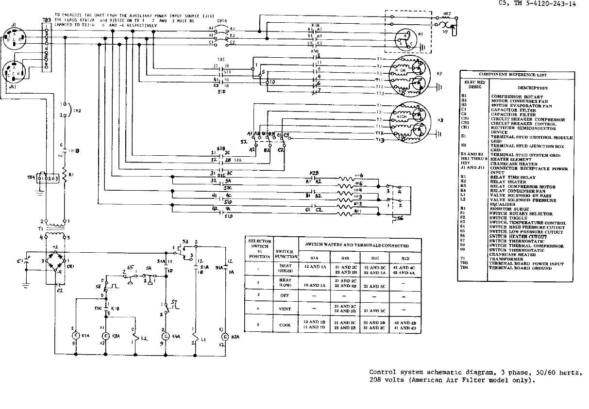
• For missing or . E INSERT CUSTOMER WIRING INSTRUCTIONS.
Please contact HUSKY for further assistance. VAC Air Compressor Wiring Instructions.*Air Tools: O-Rings and driver blades are considered ordinary wear parts, therefore, they are warranted for a period of 45 days from the date of purchase. o An air compressor that pumps air more than 50% during a one hour period is considered misuse because the air compressor is undersized for the required air demand.
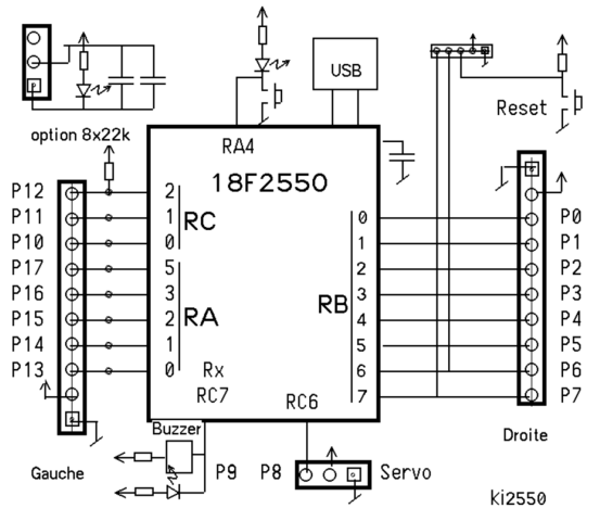
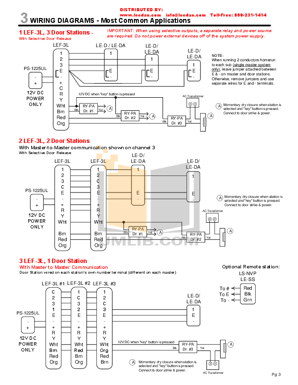
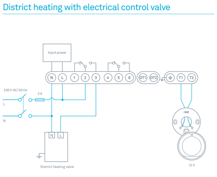
Volt Air Compressor Wiring How to Wire a Volt Air Compressor: With a standard volt motor for equipment such as an air compressor there are only two insulated wires for the / volts and one separate wire for the ground. 7.
Position compressor next to air tank with leader hose partially threaded into check valve. 8.
Mark feet position of both compressor and air tank. 9. Using these marking, drill holes for mounting.
With compressor and tank mounted connect steel leader hose to check valve. Using diagram mount and wire solenoid and circuit breaker.
If ordered with a factory mounted magnetic starter, compressor is wired at factory. It is necessary only to bring lines from a properly sized disconnect switch to the magnetic starter mounted on the unit.
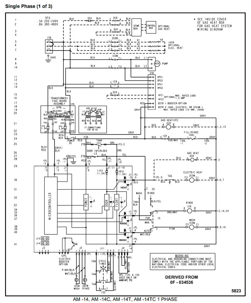
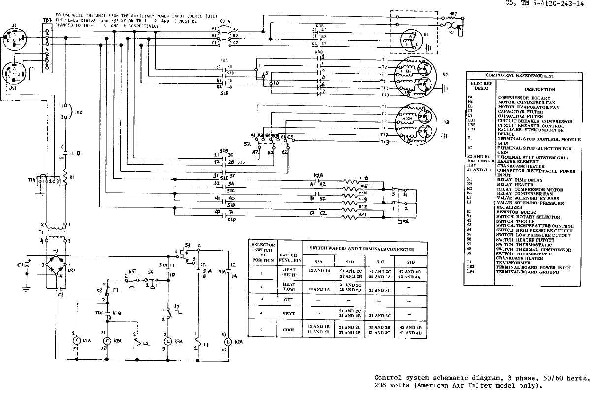
Figure 1 – Simplex Wiring Diagram CASB (Ref. Drawing) CASA (Ref.
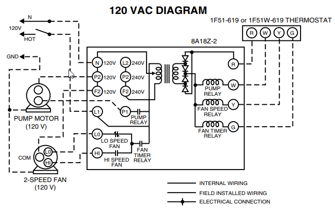
Drawing) MCGUIRE AIR COMPRESSORS The wiring diagram identifies the fan motor and compressor’s wire colors and functions. A wiring chart on the fan motor’s case also identifies the fan motor’s wire colors and each wire’s function. The letters stamped into the compressor’s housing near the wire terminals identify each terminal function.Wiring A Compressor Pressure SwitchDEVILBISS FA OWNER’S MANUAL Pdf Download.
