
Parker Hannifin assumes no liability for typographical errors or other errors.
E- Index. Machines Parkrimp® 2. Ec Crimp Charts.
KarryKrimp® 1 / Parkrimp® 1. Ed-1 – Ed KarryKrimp® 2 3 steel wire braided hoses up to size .. Hose Cutting Machine TH / 3-phase, Volt.
Electrical Ed Crimp Chart. 2.
Technical Manual. Superkrimp.

Bulletin TUS. •. Read the entire .
Superkrimp crimper with volt, 3 phase power unit .. Parkrimp Series.
9. Parkrimp machines are simple to .
supplied by Parker Hannifin for the express purpose of operating the crimper. .
Caution: Read the operations and technical manual before attempting to operate this machine. Do 3/8”, 1/2”, 3/4”, 1” and 1- 1/4” and 77 Series dies in sizes.
1/2” . / volt, 3 phase, 50/60 Hz power.
Parker – crimping video
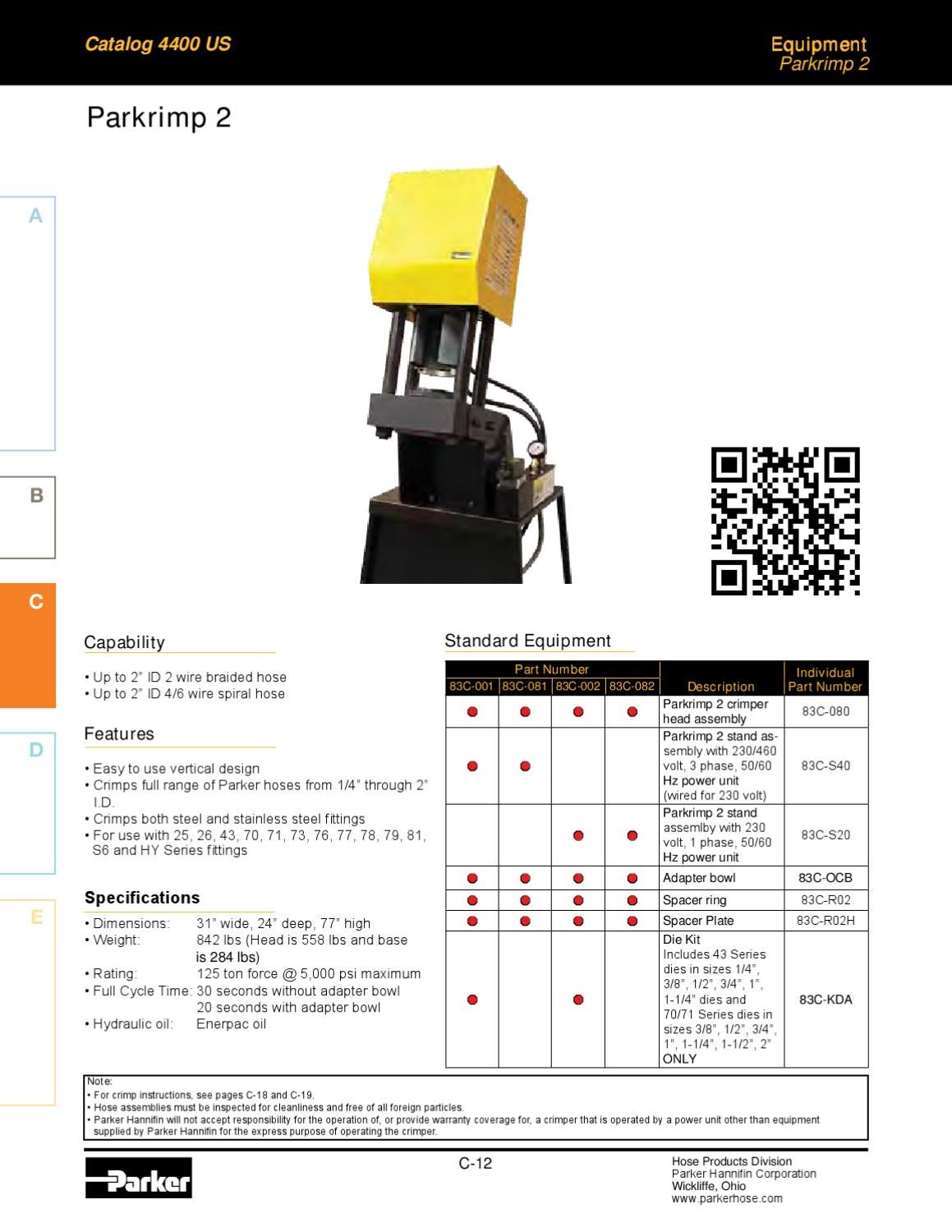
C Equipment. Catalog US. A.
B. A. C.
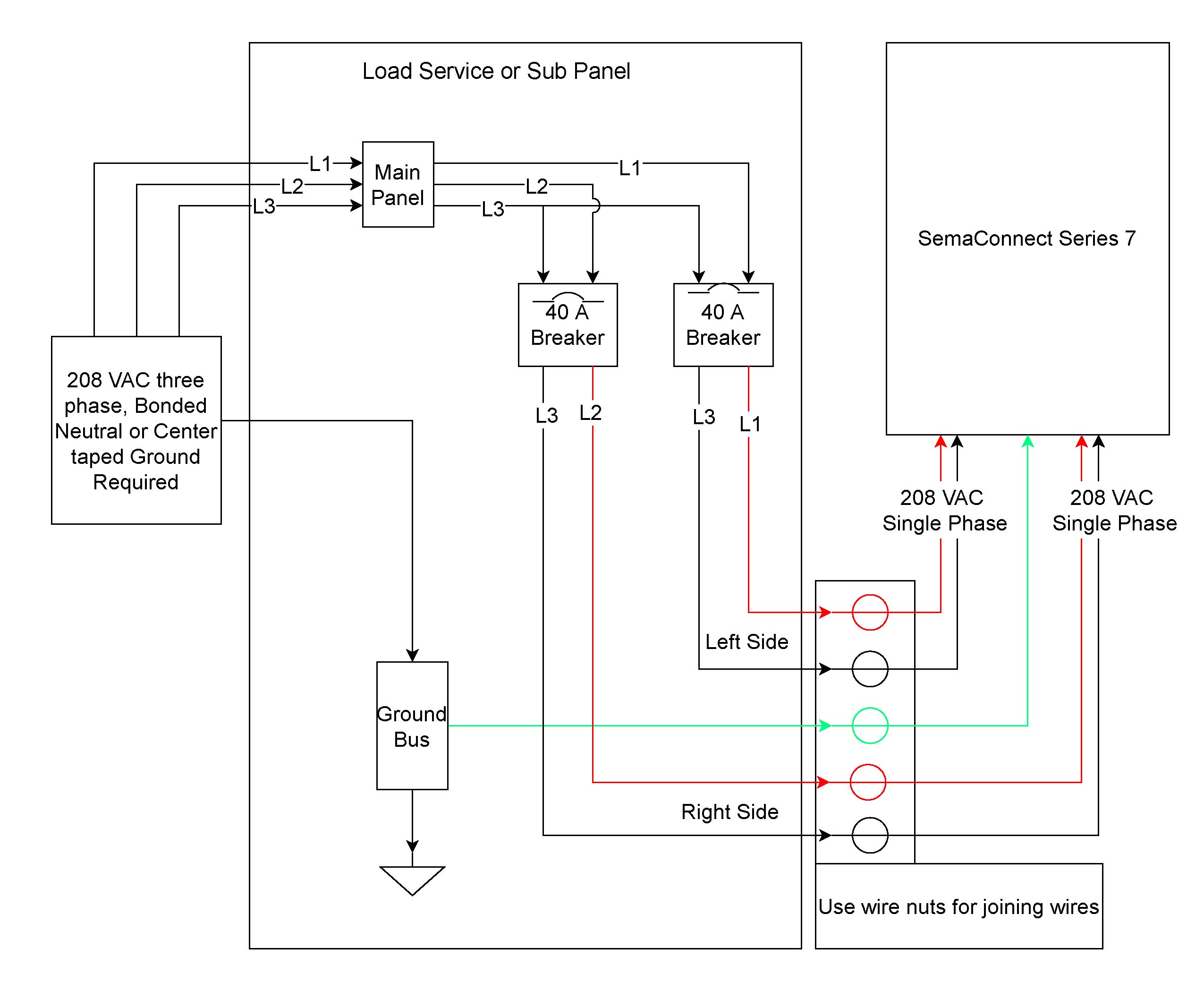
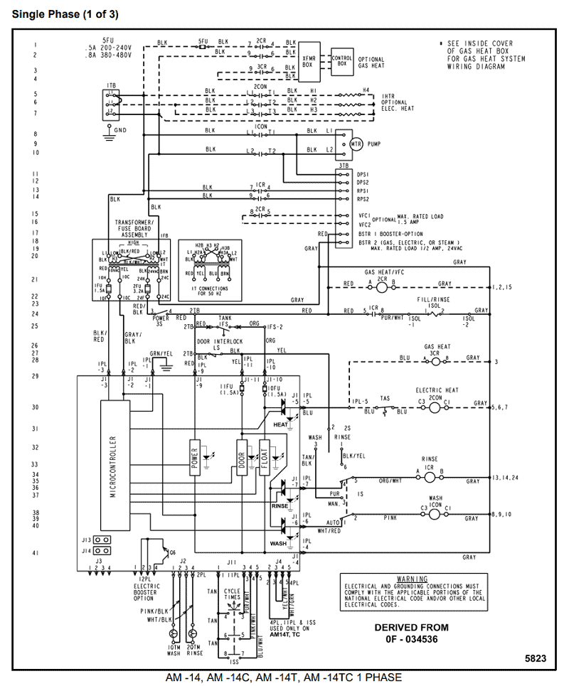
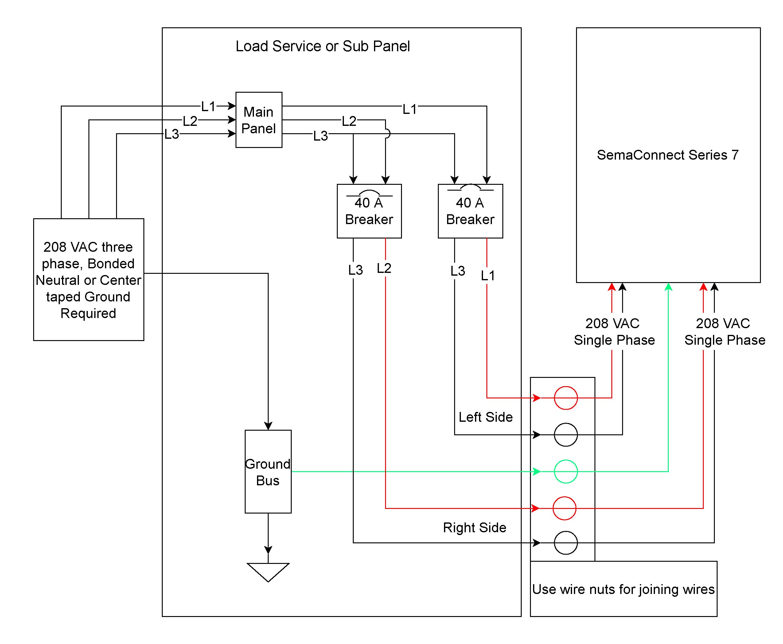
Wiring of 3 Phase Distribution Board from energy meter-3 Phase DB Wiring Diagram with MCB Connection
D. E.
Hose Cut-Off Machine. and C C Hose Products Division.
Parker Hannifin Corporation. Wickliffe, Ohio the Parkrimp family of crimping machines .
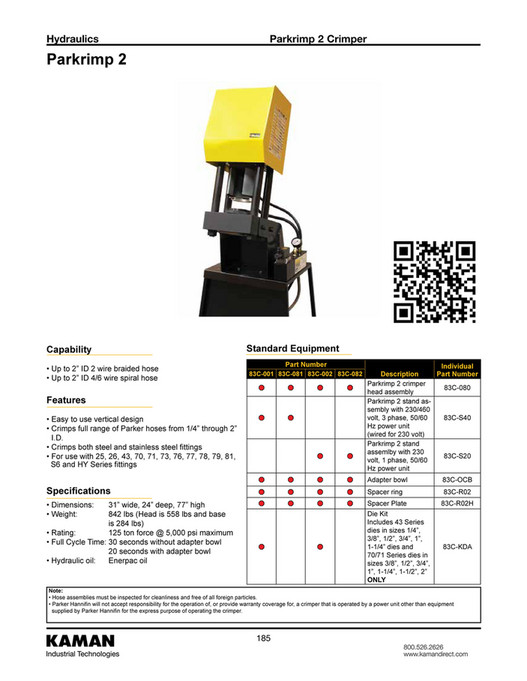
83C-081 Parker Parkrimp 2 Hose Crimping Machine
SILVER. Caution: Read the operations and technical manual before attempting to ..
volt, 3 phase, 50/ TH Hose Assembly Test Bench. TH 7-stage hose reel. Hydraulic Hose Assembly Workshop Equipment.
TH the ParLock hose and fitting range, Parker meets this demanding . Parkrimp® 2.
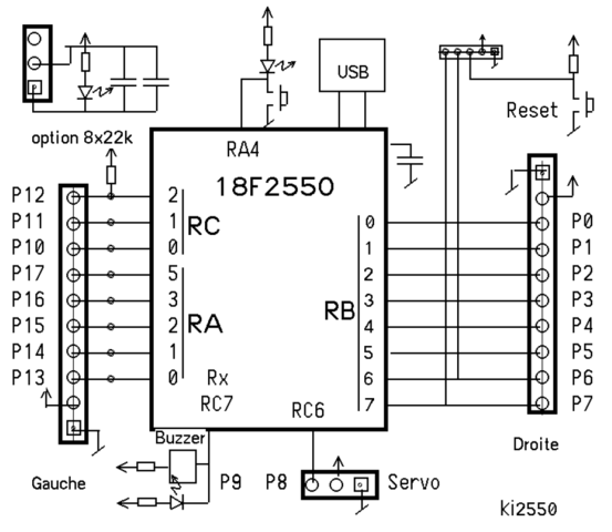
Ec Crimp Charts karrykrimp® 1. Ed-1 – Ed-4 karrykrimp® 2 3 steel wire braided hoses .up to size Jul 24, · I thought I would post this here first rather than sign up for another forum. I have a mid ‘s Parker Fly Deluxe with piezo bridge.

During a repainting job the wires of the batter holder came off the PCB and I need to find out which contacts to solder the wires back on to. Parker Hannifin S.p.A S.B.C.
Division SLVDN User’s Manual Par. Description Field Def. b Electronic CAM2 engaging on master phase 0.
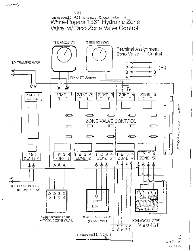
b Electronic CAM2 release on master phase 0. b CAM 2 engaging immediately (Signal lock/Unlock CAM 2).
. Parker Hannifin Corporation Hose Products Division Wickliffe, OH 2 Technical Manual Superkrimp Bulletin TUS • Read the entire Technical Manual prior to mounting and operating this crimper.
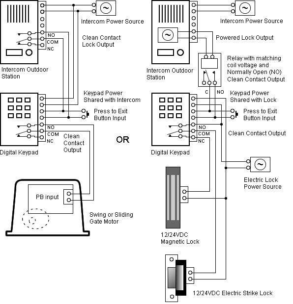
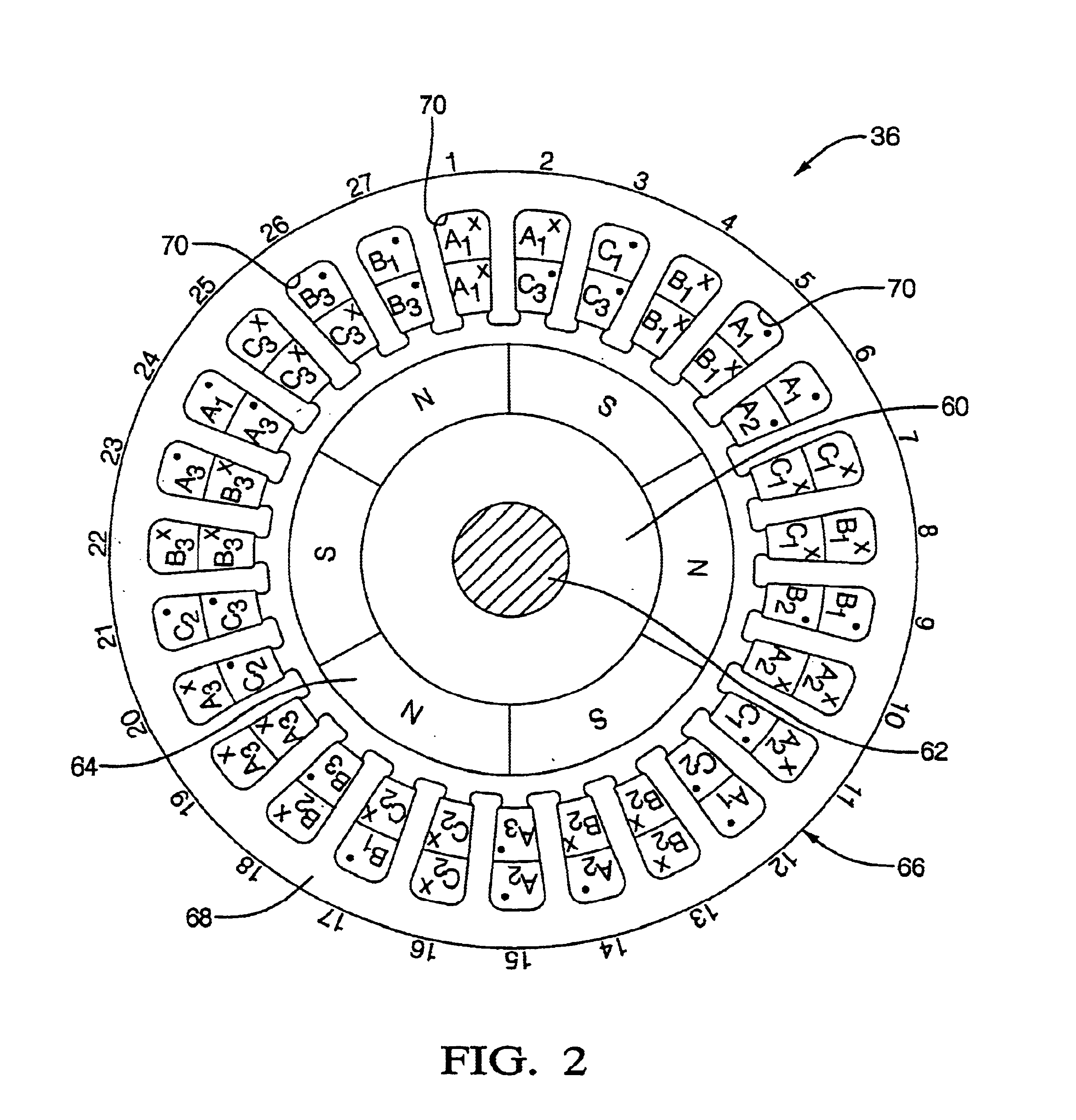
Connect your motor cable’s phase wires 1, 2, and 3 to the drive’s U, V, W terminals, respectively, as shown in the drawing below. For wiring diagrams, color codes, dimensions and speed/torque curves for Compumotor motors, consult the separate Gemini Motor Reference Manual.

in hi-flex cables do not match the above wiring diagram. Contact Compumotor for wiring diagram. Phase A J Black 1 Phase B K Black 2 Phase C L Black 3 Ground M Green/Yellow Pin Number Wiring and Cable Specifications (Continued) Encoder +5 H Red Encoder Ground G Black CH A + A White.Step-By-Step Hydraulic Hose Assembly | Parker Hannifin Hose ProductsParker Fly Deluxe Wiring Diagram | Fractal Audio Systems Forum
