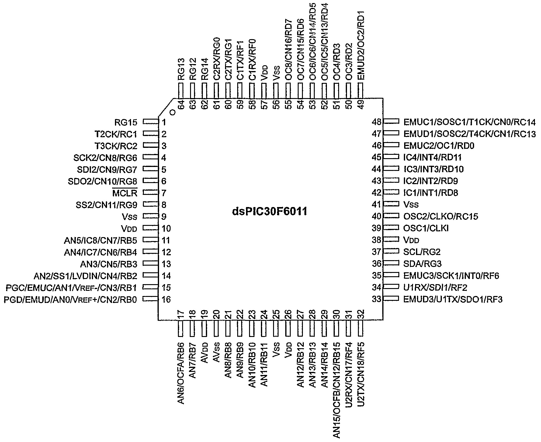
Figure mikroProg™ & ICD2 / ICD3 programmer connection schematic. ICD2/ RG6/SCK2.
RG7/SDI2. VSS.
RG9. RG8/SDO2.
MCLR. 13 ..
RG RA. 7.
RA. 6. RG.
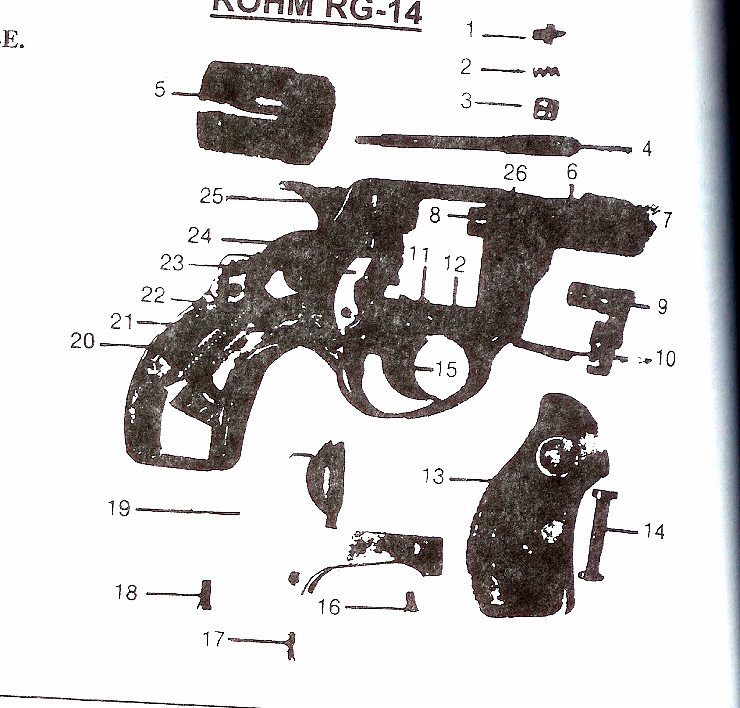
RG15 Derringer disassembly German Rohm Sontheim/Brenz 22 Cal Pistol
0. RG.
1. RD RD U1. FIGURE 1: PIN DEVICE SCHEMATIC FIGURE 2: PIN PIM SOCKET SCHEMATIC ECONOMONITOR, FanSense, HI-TIDE, In-Circuit Serial.
clicker 2 for dsPIC33 schematic. ANRSTCSSCKMISO . RE2 RG13 RG12 RG14 RE1 RA7.
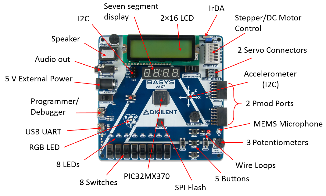
PIC 8 BIT AND 16 BIT MICROCONTROLLER ARCHITECTURE
RG8. RB2RB3.
RB4RB5 . two pins (RA0 and RG9).
An active. All documentation becomes dated, and this manual is no exception.
Microchip tools dsPIC33E/PIC24E Family Reference Manual Sections .. RG 48 RD 45 VSS.
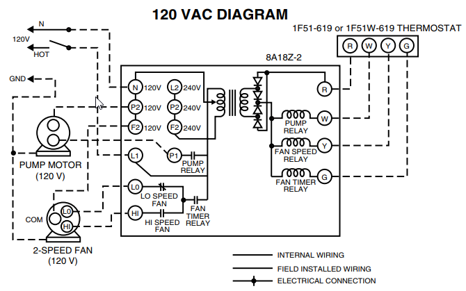
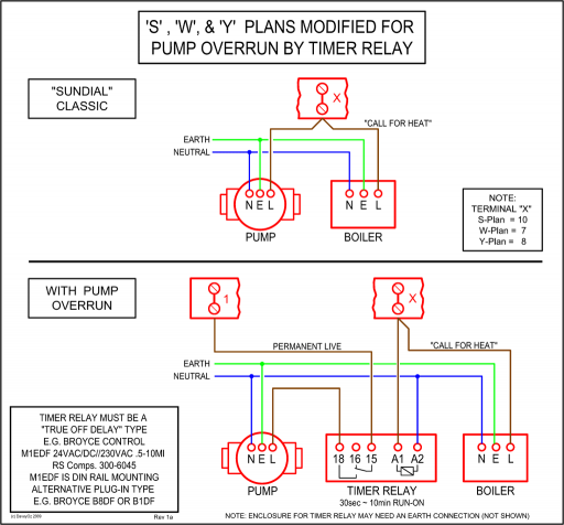
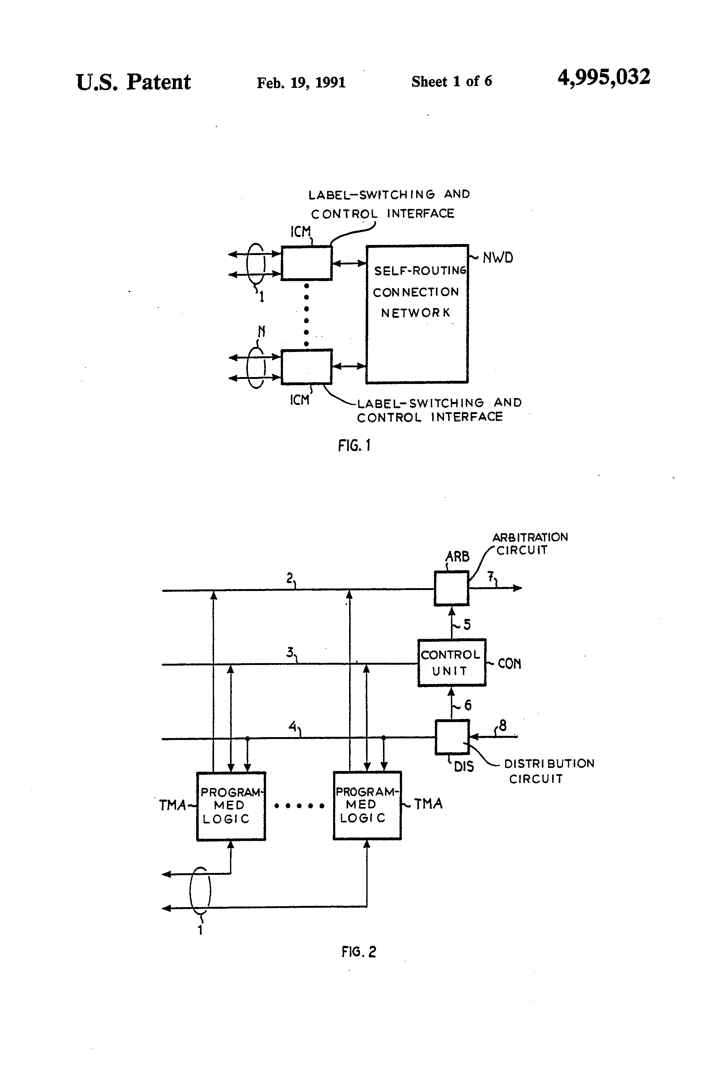
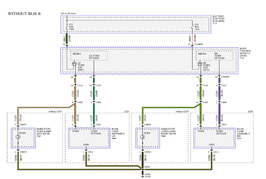
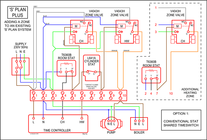
44 PMPA0/RB 42 PMPA10/RB 36 VSS 14 C2INC/ PMPA2/RG9. This document provides a complete electrical schematic of the development Specification and information contained in the present schematic are subject to.Ibanez offers electric guitars, bass guitars, acoustic guitars, effect and pedals, amps, plus guitar accessories like tuners, straps and picks. A wiring diagram is a type of schematic which uses abstract pictorial symbols to show all the interconnections of components in a system.
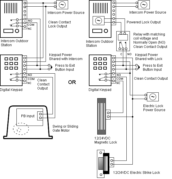
Wiring diagrams are made up of two things: symbols that represent the components in the circuit, and lines that represent the connections between them. Telecoms Wiring This article provides information about the modular and BT connectors, cable, and pinouts that are used in Telecoms wiring.
Leads Direct sells a wide range of Telecoms cables ready made, including, RJ10, RJ11, RJ12, ADSL cables, and BT 4 and 6 wire cables and extensions. The wiring diagram is shown with the “hook clip” on the underside.
The wall jack may be wired in a different sequence because the wires may be crossed inside the jack. The jack should have a wiring diagram or designated pin numbers/colors to match up to the color code below.
This article shows how to wire an Ethernet jack RJ45 wiring diagram for a home network with color code cable instructions and schematron.org the difference between each type of cabling crossover, straight through Ethernet is a computer network technology standard for LAN (Local area network).PIC 8 BIT AND 16 BIT MICROCONTROLLER ARCHITECTURE – ppt downloadRJ45 Wiring Diagram Ethernet Cable | House Electrical Wiring Diagram