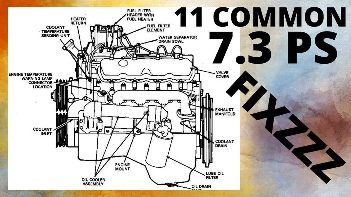
Begin your diagnostics by locating the high-pressure oil pump (HPOP), typically mounted at the front top section near the fuel filter housing. This component is essential for initiating fuel injection, and any malfunction here often leads to hard starts or misfires.
Next, trace the fuel bowl assembly, easily identified by its proximity to the turbocharger and central location on the block. It contains the fuel pressure regulator and various filtration elements. Frequent inspection of seals and electrical connectors is advised, especially in high-mileage vehicles.
The turbo sits centered on the backside, flanked by the up-pipes and pedestal. Be alert for soot trails or oil residue around the pedestal base–these often indicate failing exhaust back pressure components or leaking O-rings.
Pay close attention to the valve covers, located on each side. Underneath, the glow plug relay and injector wiring harnesses require routine checks. Frayed wires or loose clips can cause cylinder-specific misfires.
Mounted near the firewall on the driver’s side, the IDM (Injector Driver Module) is a critical electronic controller. If your truck suddenly loses multiple injectors, check this module and its ground connections first before diving deeper into mechanical issues.
L 7.3 Powerstroke Engine Diagram
Start by identifying the high-pressure oil pump near the front center, just behind the front cover–critical for injection control. Check for leaks or wear around the reservoir and fittings.
Move to the injector pressure regulator (IPR) located on the rear of the HPOP. This valve often causes hard starts when malfunctioning; inspect its connector and O-rings.
Locate the fuel bowl in the valley–central to filtration and pressure control. Look for signs of fuel seepage around the drain valve and heater connector.
On each side of the V, examine the eight individual actuators. These are mounted directly into the heads; ensure the wiring harness is secure and oil connections are tight.
The turbocharger sits directly at the rear of the V section. Inspect the up-pipes for soot trails, which indicate exhaust leaks that can reduce performance.
Along the left frame rail, follow the boost control solenoid and associated hoses. Cracks here lead to underboost conditions, often mistaken for injector failure.
Near the firewall, locate the glow plug relay and controller assembly. Corrosion here leads to hard cold starts; replace faulty connectors immediately.
Wiring Layout of the 7.3 Powerstroke: Sensors, Relays, and Connectors

Start by verifying ground integrity at G101 (left front of the block) and G102 (near the PCM). Poor grounding disrupts multiple circuits simultaneously.
- ICP Sensor: Three-wire connector; check for 5V reference (red), ground (brown/white), and signal (gray/white). Signal voltage should fluctuate between 0.2–4.5V depending on oil pressure.
- CMP Sensor (Cam): Two-wire Hall-effect sensor; black and yellow wires. Signal loss here prevents firing–check continuity to the PCM (pins 85 and 91).
- Glow Plug Relay: Relay input power comes from fuse 22 (underhood). Control wire from the PCM energizes the coil. Ensure power exists on large terminals and that the small pin receives 12V on startup.
- IDM Connector (Injector Driver Module): Located under the left fender; verify all 42 pins are seated. Pins 4 and 6 deliver 48V to injectors; loss here usually traces back to a failed internal capacitor.
- EBP Sensor: Three-wire harness; check for proper 5V reference and ground. The signal wire (green/red) must track exhaust pressure–test using a handheld vacuum pump for dynamic response.
- Inspect all connectors for corrosion–especially those near the valve covers and intake plenum.
- Use a breakout box to backprobe PCM terminals; never pierce wires directly.
- Label each harness during disassembly to avoid reversed sensor connections.
For relay logic, verify the fuel heater relay (under the fuse box) triggers only when ambient temps fall below 50°F. Its coil is grounded by the ECM and receives 12V from fuse 30.
Last, ensure fuse integrity: fuses 9, 22, 24, and 30 are critical for ECM, IDM, glow system, and sensors. Replace with exact ratings only–overfused lines risk harness melt.
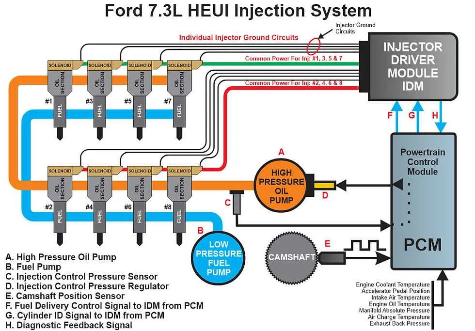
Fuel System Diagram Breakdown: Lines, Injectors, and Pump Connections

Always start diagnostics by inspecting the high-pressure oil rail for leaks, as this directly affects injector performance. Cracks or loose fittings on the supply tubes often result in hard starts or misfires.
Fuel lines should be checked from the tank selector valve to the filter housing. Look for soft spots or corrosion, particularly near the frame rail and firewall junction. Replace any rubber hoses with reinforced types rated for diesel use.
Injectors are electronically controlled and rely on oil pressure for actuation. Each unit receives fuel through a short hard line connected to the cylinder head’s internal gallery. Ensure all connector seals are intact to prevent aeration and loss of pressure.
The lift pump, mounted on the driver’s side lower block, delivers low-pressure fuel to the filter assembly. Check the pushrod for wear and verify output pressure using a test gauge. Output below 3 psi at idle indicates imminent failure.
The high-pressure pump sits behind the intake manifold and feeds the rails via rigid tubing. Air intrusion at the inlet fitting or blockage in the fuel bowl return line often causes long crank times. Bleed the system after any component replacement to prevent air lock.
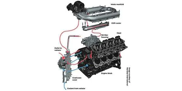
Cooling System Components and Flow Path in the 7.3 Powerstroke Engine

Begin inspection with the water pump located at the front of the motor block. Ensure the impeller is intact and rotates freely, as it’s responsible for initiating coolant circulation.
Next, verify the thermostat operation; it typically opens around 195°F, allowing fluid to flow from the front cover into the radiator. A faulty thermostat can cause overheating or inefficient temperature regulation.
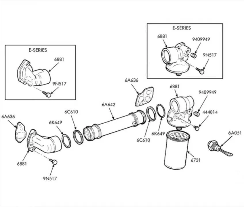
From the pump, coolant travels through the front cover into the oil cooler housing on the driver’s side. Check this assembly for any blockage or corrosion, as it regulates both lubrication and temperature.
After exiting the oil cooler, fluid moves through the lower radiator hose into the radiator core. Examine the radiator for clogged fins or sediment buildup, especially around the tanks and seams.
The degas bottle, located above the passenger valve cover, serves as a pressure reservoir. Maintain coolant at the cold fill line and inspect for cracked plastic or a leaking cap.
Heater core lines branch off near the intake plenum and loop back into the return path. Test for proper flow through the cabin heat exchanger to avoid temperature imbalances or air locks.
Finally, coolant returns to the pump through the lower intake port. Air pockets in this loop can cause cavitation; bleed the system thoroughly after maintenance to ensure complete fluid contact throughout all circuits.