Note: These Instructions are for VDO Gauges and Accessories only. Click here for Auto Electronic Programmable Speedometer, Electronic.
Now, any VDO electronic speedometer can be an incredibly accurate GPS-driven speedometer. With the VDO GPS Speed Sender, there are no cables required. Note: These Instructions are for VDO Gauges and Accessories only.
Click here for Auto Electronic Programmable Speedometer, Electronic. Now, any VDO electronic speedometer can be an incredibly accurate GPS-driven speedometer.
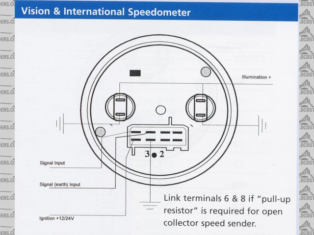
With the VDO GPS Speed Sender, there are no cables required. VDO cockpit vision VDO cockpit international .
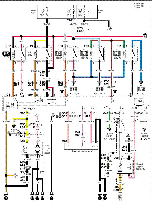
Wiring diagrams. 2 – 9 The electronic speedometer should be installed by a Mannesmann VDO Kienzle.Wire and Wiring Harnesses; Warning Buzzer; Warning Indicator Lights; Wire & Wiring Harnesses; kmh 4″ (mm) Electronic Speedometer with Autocalibration, 12/24V Learn More. ViewLine Silver MPH /8″ Speedometer with GPS Speed Sender Find a VDO authorized distributor.
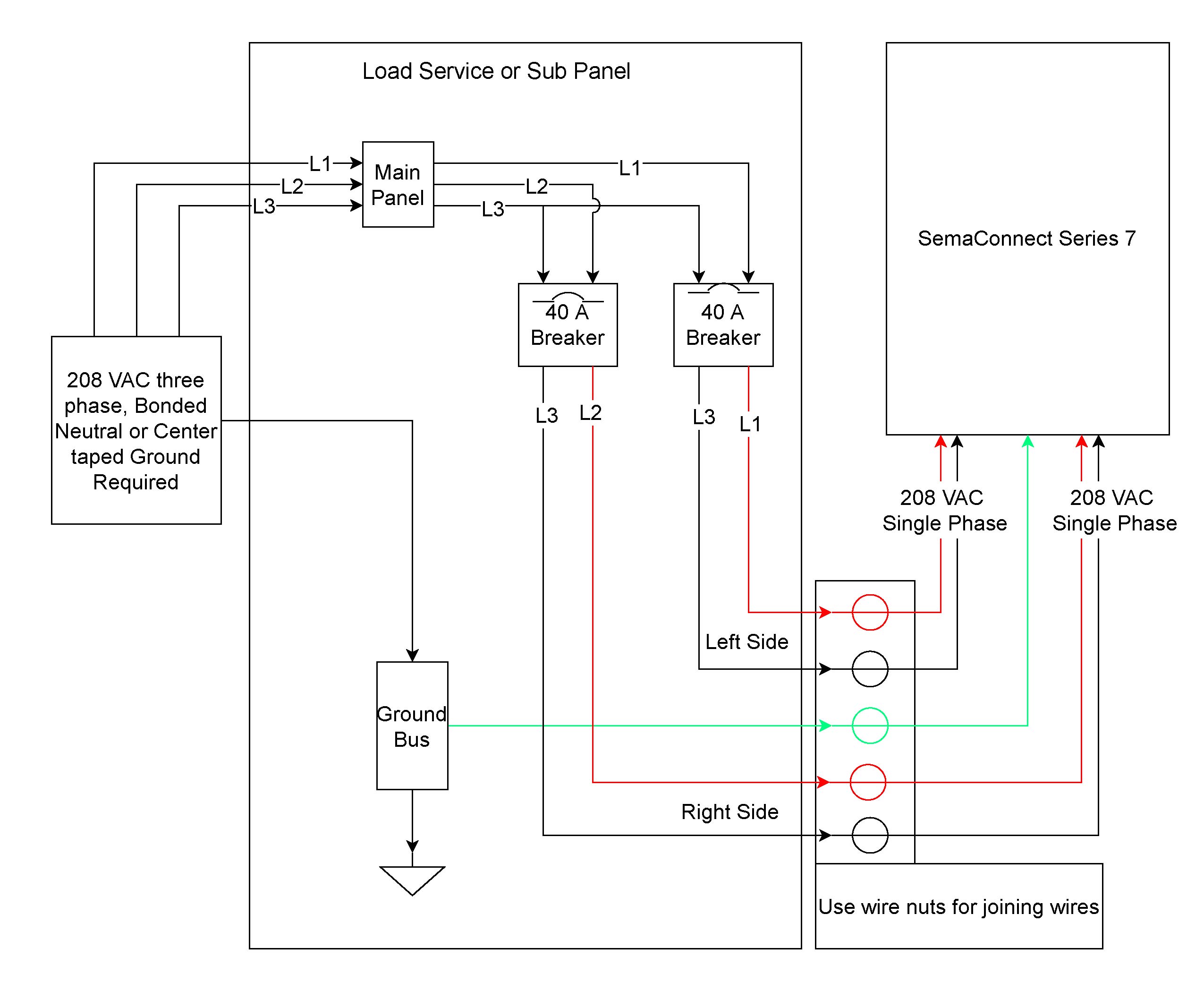
sions and damages to other electronic systems. Consequently, all power supply cable connections must be provided with weldable connectors and be sufficiently insulated.
† Ensure ground connections are sound. † Faulty connections can cause short circuits.
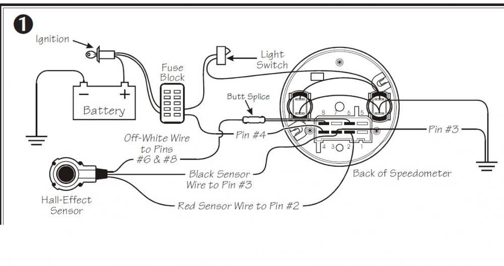
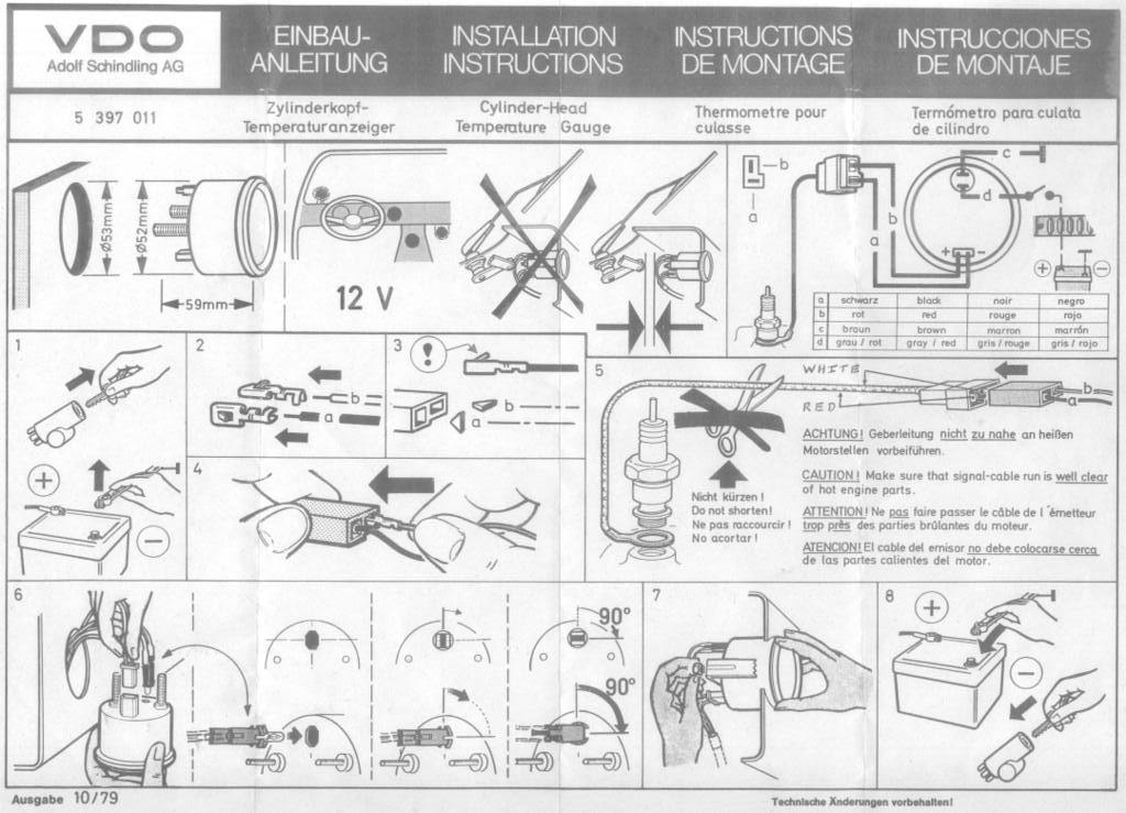
Only connect cables according to the electrical wiring diagram. 0 electronic speedometer hall effect sender installation instructions and wiring diagram 7udqvplvvlrq type a speedometer 4-wire system 5(’:+,7.
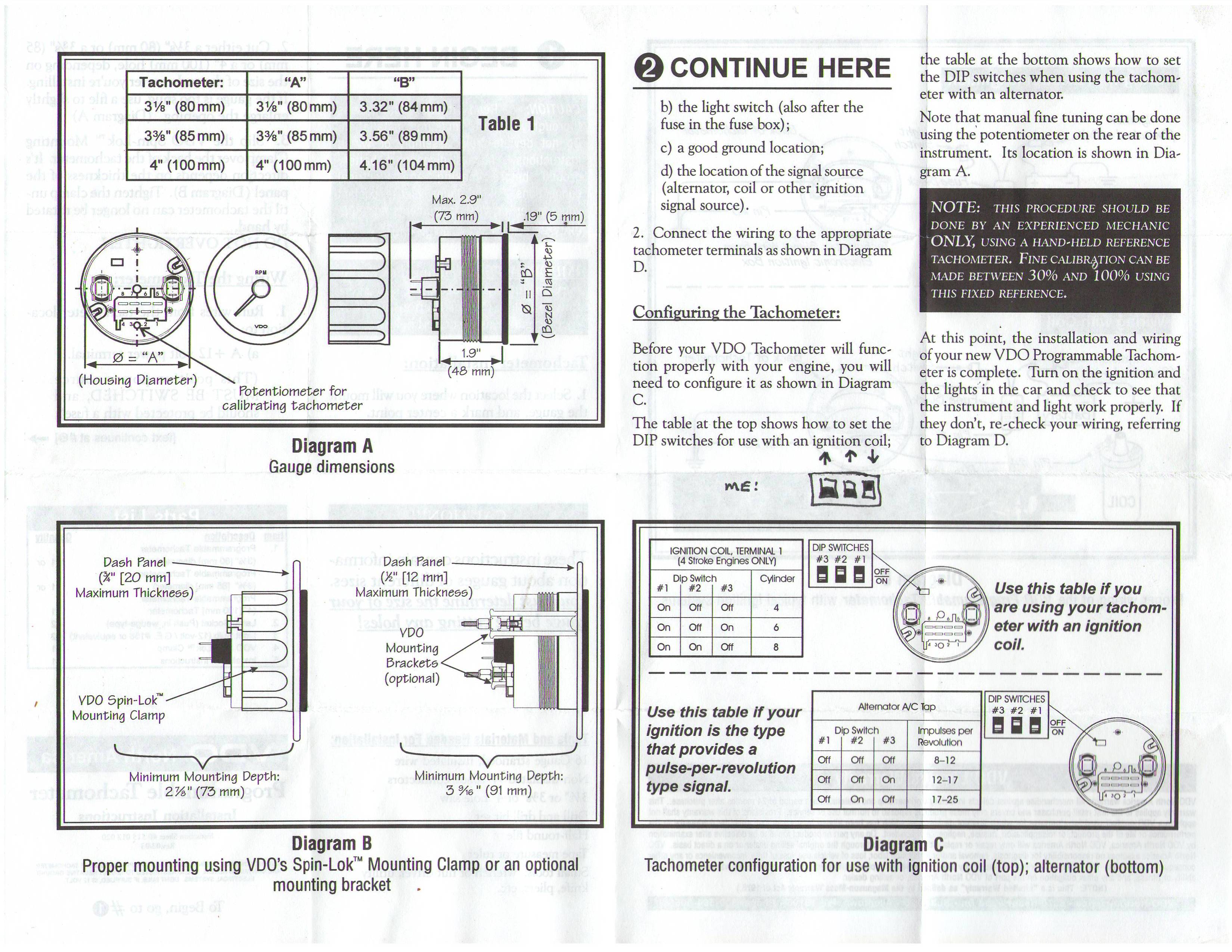
junction, and attach the wire from the speedometer. Refer to Diagram D for the proper wiring of the speedometer.
3. Attach the wire from pin #3 to a ground (negative) source.
One such source can always be found where the battery is attached to the metal frame of the vehicle. Use an appro-priate electrical connector to ground this wire.
4a. There are 3 holes, I’ll refer to them as 1, 2, and 3 left to right.
1 and 3 are along the same plane, 2 is a little over 71mm below that. If you make a template, draw a line mm long mark hole #1 center 5mm from the left end of the line measure mm along the line from hole #1 center and mark hole #3 center.VDO Performance InstrumentsVOLVO V50 OWNER’S MANUAL Pdf Download.
