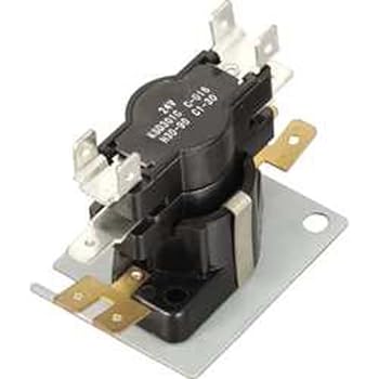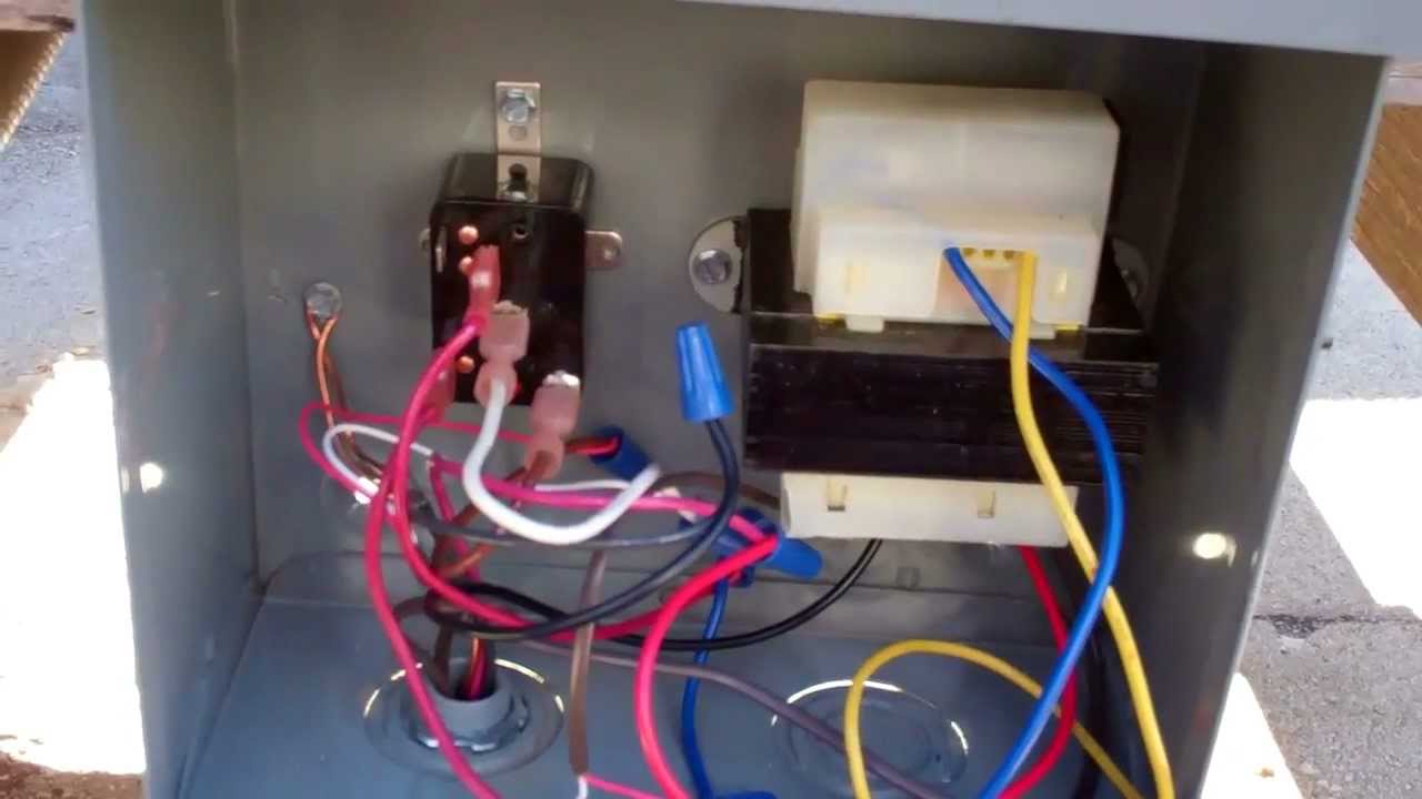
Model #11097281100 Kenmore residential dryer
Prior to installation, thoroughly familiarize yourself with this Installation Manual. Observe all safety conductors as shown in the unit wiring diagram using. ” (mm) printed circuit; silver-cadmium oxide, 10 amps.
.. (). 1 2 3 4.
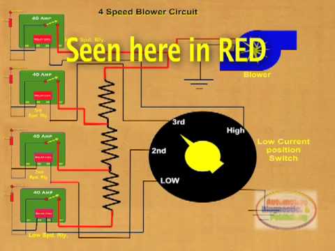
HVAC Relays- The ICM277C Blower Control Board
Wiring Diagrams. Printed. Circuit” (mm).
Quick Connect. Note: All.
goodman blower time delay relay wiring | tricia industrial relay bs wiring diagram – complete pdf l | goodman | m | johnstone supply. B, HEAT RELAY, , , , M, RELAY, WCK, 03/01 / B, WIRING DIAGRAM C48/, OBSOLETE, ITEM NO LONGER. SUBJECT: Potential Incorrect Fan Wiring on ASUF and ASPT Air Handlers.
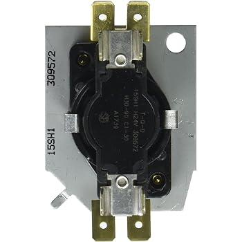
We have M relay is used; see the pictures on the right.wiring diagram (heat pump) obsolete: item no longer available: 05/21/ bh: high temp drain pan: obsolete: item no longer available: 05/21/ b flowrator: obsolete: item no longer available: 05/21/ b ck/flowrater a24,cp obsolete: item no longer available: 05/21/ b flowrater. REPAIR PARTS RPC This manual is to be used by qualified technicians only. This manual replaces RPB.
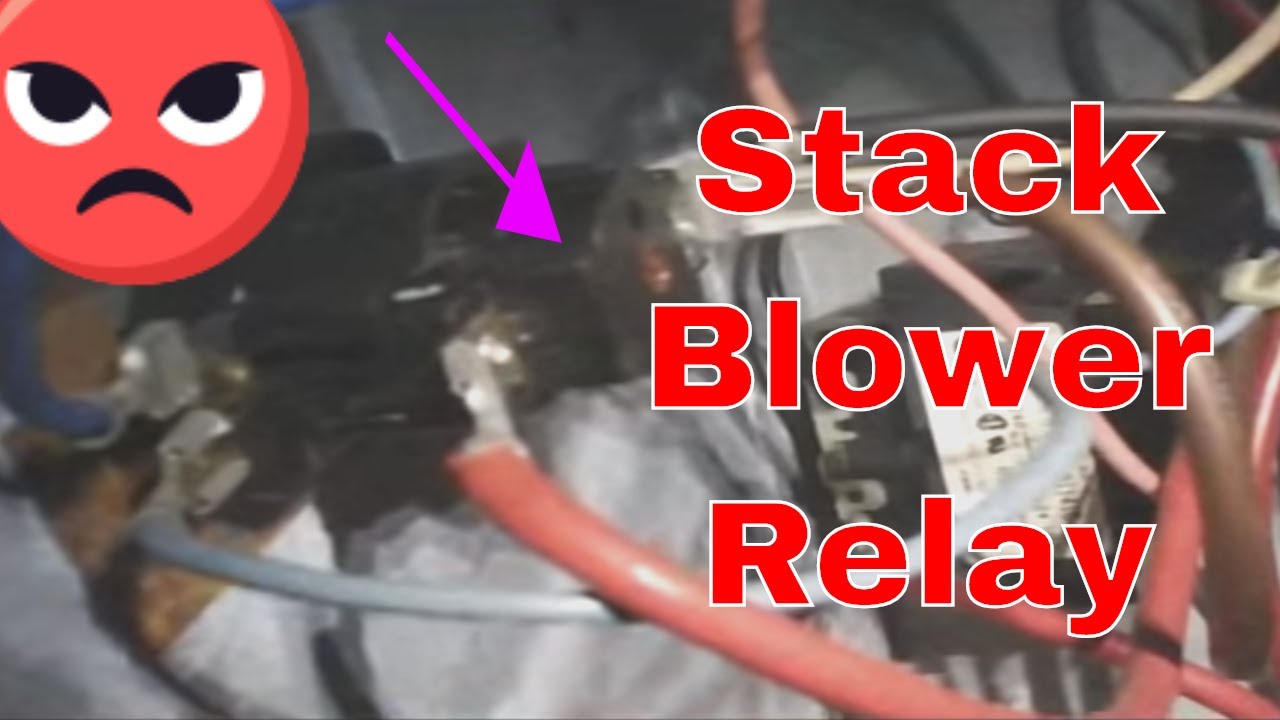
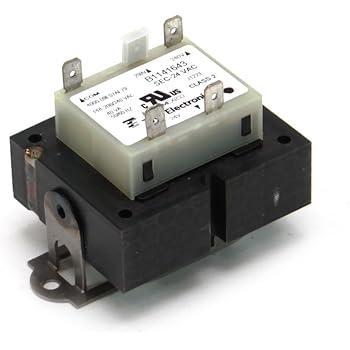
M RELAY, WCK M TERMINAL BOARD M TRANSFORMER, /, 24V M RELAY, WCK AP WIRE ASSY, 9 PIN FEMALE CONN. AP WIRE ASSY, 9 PINN MALE CONN.
Goodman Furnace Tech Support
If your Guaranteed Delivery item isn’t on time, you can (1) return the item, for a refund of the full price and return shipping costs; or (2) keep the item and get a refund of your shipping costs (if shipping was free, get a $5 eBay voucher).Seller Rating: % positive. REPAIR PARTS RPD This manual is to be used by qualified technicians only. This manual replaces RPC. M RELAY, WCK AP WIRE ASSY, 9 PIN FEMALE CONN. AP WIRE ASSY, 9 PINN MALE CONN.
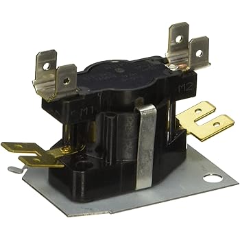
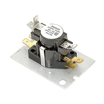
APDG Drip Shield, Ptd (M1, M2). Replacement relay for the original White Rodgers relay. Terminals 4 & 7 are normally open while terminals 4 & 1 are normally closed. When 24V terminals A and B .AWUF Vertical Mount Air Handler – All Aluminum – PDFWiring Diagrams
