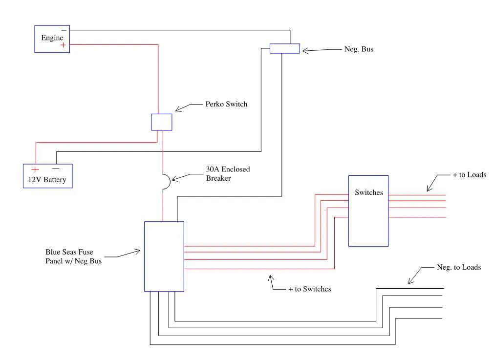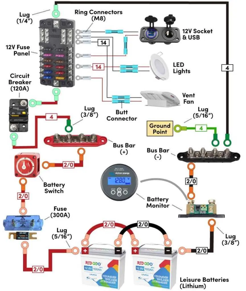
To properly set up your marine electrical system with a trio of energy sources, ensure that each unit is wired in parallel for efficient performance. This approach allows each element to share the load evenly, ensuring steady power distribution. It’s critical to ensure the correct polarity during the connections; reversing leads can cause damage to components and even present safety risks.
Start by connecting the positive terminals of each source together, then link them to the power distribution system. The negative connections should also be joined in a similar manner, ensuring a solid ground path. For optimal performance, always use cables rated for high current capacity to handle the combined output safely.
For best results, incorporate a switch to isolate the sources when necessary, especially if maintenance or troubleshooting is required. A fuse or circuit breaker should be installed to protect the system from overloads. Never forget to verify the integrity of connections and regularly check for corrosion that can impair the system’s efficiency.
Optimized Power Distribution Setup for Triple Energy Sources

For a setup with three separate energy cells providing power to your vessel, the most efficient configuration is to connect the units in parallel. This ensures a balanced charge and increases the total available amperage. Use a reliable switch to alternate between the power sources, ensuring each gets an equal share of usage. Install a reliable isolator to prevent cross-contamination of charge between the units. The isolator will also help protect each source from over-discharging.
Install a smart management system to monitor the charge levels of each unit. This helps in tracking the health and efficiency of the individual sources. Wiring the isolator directly to the main distribution panel ensures a smooth switch-over when changing power sources, preventing any voltage drops or sudden surges in current that could cause damage to sensitive components. It is important to use high-quality marine-grade connectors and cables to ensure corrosion resistance and longevity of the entire setup.
Position the power units to minimize the length of connections, which reduces energy loss and maximizes efficiency. If your vessel is equipped with a DC-to-AC inverter, ensure that the total load capacity matches the power supply available from the combined cells. Always include a fuse box at the entry point of each circuit for safety, especially for high-current draws.
Understanding the Configuration for a 12V 3-Unit Power System
To ensure proper function of a 12V three-unit power system, it’s crucial to correctly arrange each component for optimal energy distribution and longevity. Here’s a guide to achieving this efficiently:
- Series Connection – When arranging units in a series, the positive terminal of one connects to the negative terminal of the next. This increases the overall capacity for prolonged usage but limits overall output to the capacity of the first unit.
- Parallel Setup – Connecting positive terminals together and negative terminals in a parallel configuration boosts the available amperage. This method ensures consistent energy supply and keeps the units charged evenly, avoiding overdrawn units.
- Mixing Series and Parallel – This advanced method can balance both voltage and capacity. One series of units feeds into a parallel system, ensuring the required load and output are met without overloading any unit.
- Proper Fusing – Each connection point must be fitted with an appropriate fuse to prevent overloads or short circuits. Ensure the fuse rating matches the expected draw for safety and efficiency.
- Quality Cables and Connectors – Use corrosion-resistant materials for connectors. Ensure cables are thick enough to handle the load to prevent overheating or degradation over time.
Implement these configurations based on your system’s specific needs to achieve reliability and efficiency, optimizing the flow and use of power in any application.
Step-by-Step Instructions for Connecting the Power Units and Electrical System
1. Begin with proper safety measures: Before starting, ensure all power sources are disconnected. Wear rubber gloves and safety goggles. Double-check that no live wires are exposed.
2. Position the energy units: Place each unit in a secure, dry location with sufficient space between them. The units should be easily accessible for maintenance but not in the way of other equipment.
3. Connecting the first energy source: Attach the positive terminal of the first unit to the main power distribution panel. Use a heavy-duty cable for this connection. Tighten the connection securely to prevent any future loosening.
4. Link the remaining units: Connect the negative terminal of the first power source to the positive terminal of the second. This step is crucial for maintaining correct polarity. Repeat for the third unit, connecting the negative terminal of the second to the positive terminal of the third.
5. Secure all terminal connections: Ensure all terminals are clean and free from corrosion. Use corrosion-resistant connectors and tighten each terminal securely to avoid any loose connections.
6. Install the grounding system: The negative terminals of the units should be connected to the grounding point of your system. This ensures a stable flow of electricity and protects against possible electrical surges.
7. Verify all connections: Before powering up, check each connection to ensure everything is correct. Look for any exposed wires, loose connections, or signs of wear.
8. Power up the system: Once everything is secured and double-checked, power up the entire system. Monitor for any unusual noises, smells, or other signs of malfunction.
9. Test functionality: Test all electrical components to ensure proper operation. If everything is working as expected, proceed with regular maintenance checks to ensure longevity.
10. Final safety check: After confirming the system is fully operational, do one last check to ensure everything is stable and secure before finalizing the installation.
Troubleshooting Common Electrical Issues in a 12V 3-Battery Configuration
Ensure all connections are tight and corrosion-free. Weak or loose terminals often lead to insufficient power flow and unexpected system failures. Regularly inspect terminal connectors for any buildup of rust or grime, as these can cause poor conductivity.
Check the arrangement of cells. If one unit is wired incorrectly or not providing consistent performance, it can create an imbalance that affects the overall setup. Ensure that all connections follow a proper sequence, particularly for series or parallel configurations.
If the power is erratic, test each cell individually using a multimeter. Uneven charges or a failing component in the circuit can cause fluctuations. A failing element should be replaced promptly to avoid overloading the remaining units.
Inspect the fuse or circuit breaker. These components act as safeguards, but can sometimes fail due to constant use or environmental factors. A blown fuse or tripped breaker can disrupt power delivery and may require resetting or replacement.
Test the ground connection. A poor grounding point often leads to fluctuating or inconsistent currents, impacting performance. Make sure the grounding is solid, clean, and free of rust or other obstructions.
If charging issues arise, verify the condition of the charging system. A faulty regulator or charger can result in overcharging or undercharging, which can shorten the lifespan of the energy storage units.
Finally, regularly monitor the system with a battery monitoring tool to ensure all elements are functioning optimally. This can help detect minor problems before they escalate into more serious issues.