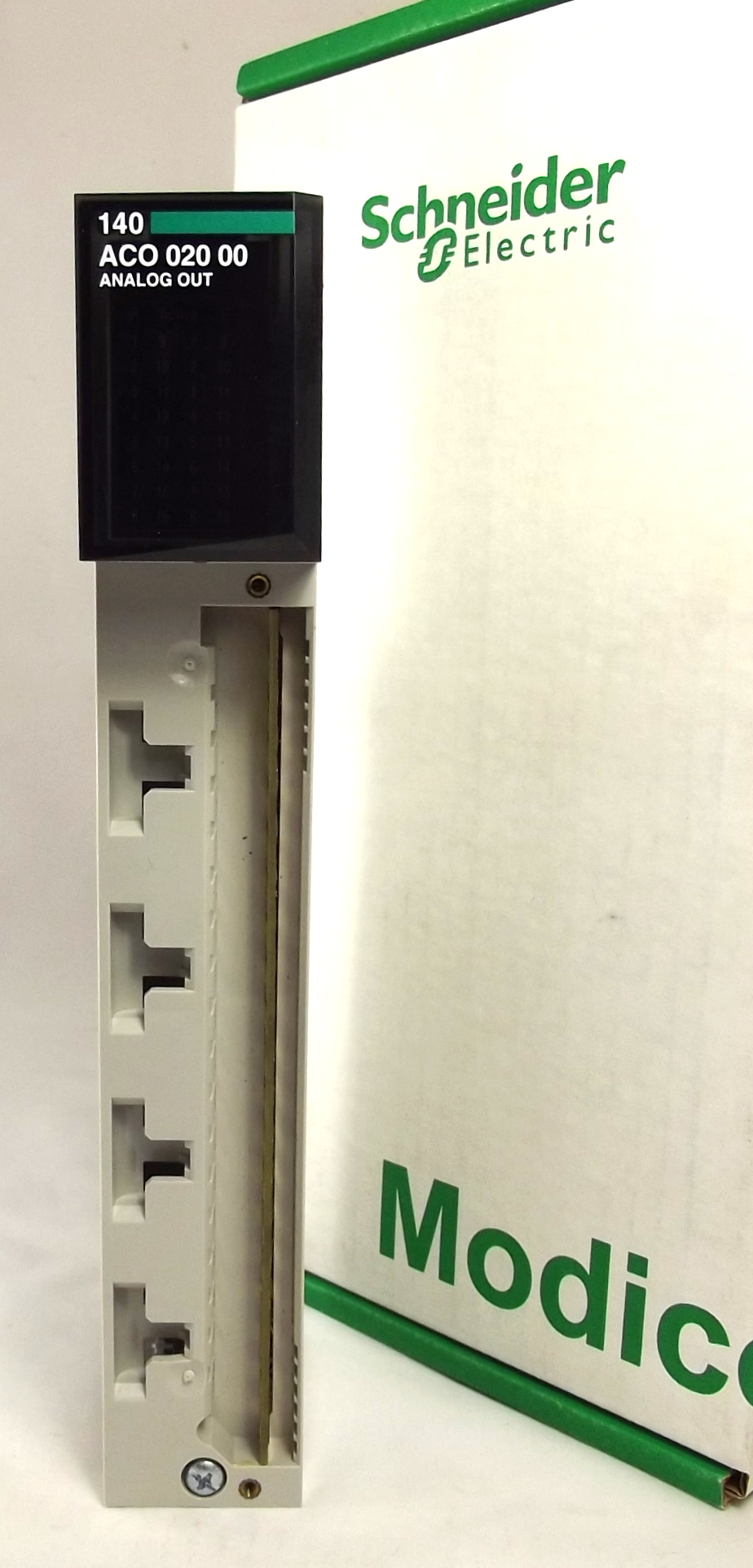
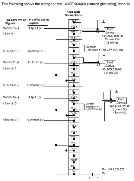
Quantum Experts and Communication Reference Manual. ○ Grounding and The following figure shows the wiring diagram for the ACO 00 module.
Quantum Experts and Communication Reference Manual. ○ Grounding and .
Schneider Electric / Modicon / Quantum 140ACO02000 Manual
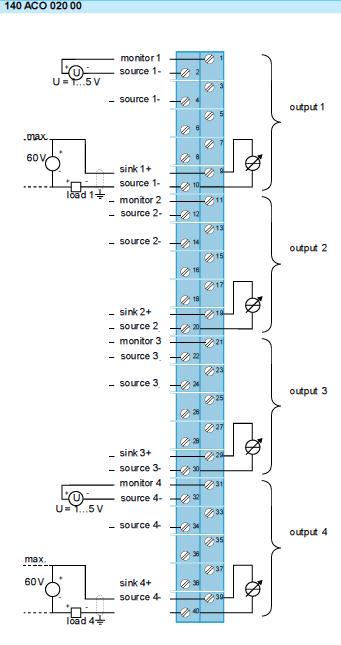
Wiring Diagram. .

Chapter 8 ACO Analog Current OUT Module. Schneider Electric / Modicon / Quantum ACO Manual .. Wiring Diagram.

Chapter 8 ACO Analog Current OUT Module. CPS 00 (PV 01 or greater) Wiring Diagram ACI 00 input module and a ACO 00 output module.
The simulator. 1.

Product data sheet. Characteristics. ACO End of life manual.
Product end of life instructions Output 4-Channel Current Module. Wiring Diagram.The information provided in this documentation contains general descriptions and/or technical characteristics of the performance of the products contained herein.
DDI New and Used available. Tested and 2-Year Warranty. Ask us about DDI Repairs.

Worldwide Shipping available. DDI ARI – analog input module Modicon Quantum – 8 I Ni / Pt , , , _00 Quantum with Unity Pro Experts and Communication Reference Manual eng June 2 Contents Discrete I/O Discrete I/O DDI 10 DDI 00 DDI 2/3 2 Optionally, you can insert mechanical keys between the I/O module and the terminal strip to ensure that the field wiring and the module type are properly matched.
Keying codes are .Product – CFK | CFK | Modicon Quantum CFK | Terminal Block Field DeviceACO | Modicon Quantum Input-Output by Modicon PLC